Integration of the ATV312 in a PROFIBUS DP network controlled by a Simatic S7©
PLC IO image / Altivar 312 DP slave mapping
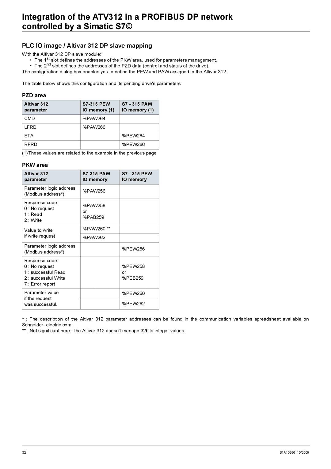
With the Altivar 312 DP slave module:
•The 1st slot defines the addresses of the PKW area, used for parameters management.
•The 2nd slot defines the addresses of the PZD data (control and status of the drive).
The configuration dialog box enables you to define the PEW and PAW assigned to the Altivar 312.
The table below shows this configuration and its pending drive's parameters:
PZD area
Altivar 312 |
| S7 - 315 PAW |
parameter | IO memory (1) | IO memory (1) |
CMD | %PAW264 |
|
|
|
|
LFRD | %PAW266 |
|
|
|
|
ETA |
| %PEW264 |
|
|
|
RFRD |
| %PEW266 |
|
|
|
(1)These values are related to the example in the previous page
PKW area
Altivar 312 |
| S7 - 315 PEW | |
parameter | IO memory | IO memory | |
Parameter logic address | %PAW256 |
| |
(Modbus address*) |
| ||
|
| ||
|
|
| |
Response code: | %PAW258 |
| |
0 | : No request |
| |
or |
| ||
1 | : Read |
| |
%PAB259 |
| ||
2 | : Write |
| |
|
| ||
|
|
| |
Value to write | %PAW260 ** |
| |
if write request | %PAW262 |
| |
|
|
| |
Parameter logic address |
| %PEW256 | |
(Modbus address*) |
| ||
|
| ||
|
|
| |
Response code: |
| %PEW258 | |
0 | : No request |
| |
1 | : successful Read |
| or |
2 | : successful Write |
| %PEB259 |
7 | : Error report |
|
|
|
|
| |
Parameter value |
| %PEW260 | |
if the request |
|
| |
| %PEW262 | ||
was successful. |
| ||
|
|
|
|
*: The description of the Altivar 312 parameter addresses can be found in the communication variables spreadsheet available on Schneider- electric.com.
**: Not significant here: The Altivar 312 doesn't manage 32bits integer values.
32 | S1A10386 10/2009 |