Hardware setup
Recommendations
•The user can select the data rate from a range of 9.6 kbps to 12 Mbps. This selection, made when starting up the network, applies to all the bus subscribers.
•The maximum segment length is in inverse proportion to the data rate.
Data rate in kbps | 9.6 | 19.2 | 45.45 | 93.75 | 187.5 | 500 | 1500 | 3000 | 6000 | 12000 |
|
|
|
|
|
|
|
|
|
|
|
Distance/segment in meters (feet) | 1200 | 1200 | 1200 | 1200 | 1000 | 400 | 200 | 100 | 100 | 100 |
| (3937) | (3937) | (3937) | (3937) | (3281) | (1312) | (656) | (328) | (328) | (328) |
•Repeaters can be used to cover greater distances.
•The bus ends with a line terminator at each end of the segment.
•Do not connect more than 32 stations per segment without a repeater, or more than 127 with a repeater.
•Keep the bus away from the power cables (clearance of at least 30 cm (11.9 in).
•If it is necessary for power cables to cross each other, be sure they cross at right angles.
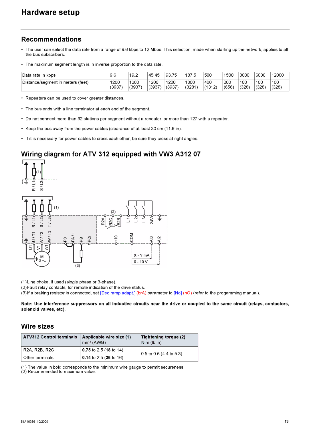
Wiring diagram for ATV 312 equipped with VW3 A312 07
(1)Line choke, if used (single phase or
(2)Fault relay contacts, for remote indication of the drive status.
(3)If a braking resistor is connected, set [Dec ramp adapt.] (brA) parameter to [No] (nO) (refer to the progamming manual).
Note: Use interference suppressors on all inductive circuits near the drive or coupled to the same circuit (relays, contactors, solenoid valves, etc).
Wire sizes
ATV312 Control terminals | Applicable wire size (1) | Tightening torque (2) | |
| mm² (AWG) | N·m (lb.in) | |
R2A, R2B, R2C | 0.75 to 2.5 (18 to 14) | 0.5 to 0.6 (4.4 to 5.3) | |
|
| ||
Other terminals | 0.14 to 2.5 (26 to 16) | ||
| |||
|
|
|
(1)The value in bold corresponds to the minimum wire gauge to permit secureness.
(2)Recommended to maximum value.
S1A10386 10/2009 | 13 |