The MSTR Instruction
3.2.2Representation
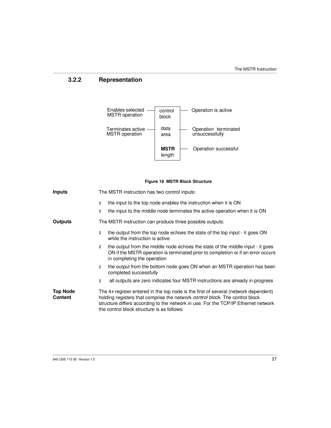
Enables selected MSTR operation
Terminates active MSTR operation
control block
data area
MSTR
length
Operation is active
Operation terminated unsuccessfully
Operation successful
| Figure 16 MSTR Block Structure |
Inputs | The MSTR instruction has two control inputs: |
| the input to the top node enables the instruction when it is ON |
| the input to the middle node terminates the active operation when it is ON |
Outputs | The MSTR instruction can produce three possible outputs: |
| the output from the top node echoes the state of the top input - it goes ON |
| while the instruction is active |
| the output from the middle node echoes the state of the middle input - it goes |
| ON if the MSTR operation is terminated prior to completion or if an error occurs |
| in completing the operation |
| the output from the bottom node goes ON when an MSTR operation has been |
| zcompleted successfully |
| all outputs are zero indicates four MSTR instructions are already in progress |
Top Node | The 4x register entered in the top node is the first of several (network dependent) |
Content | holding registers that comprise the network control block. The control block |
| structure differs according to the network in use. For the TCP/IP Ethernet network |
| the control block structure is as follows: |
840 USE 115 00 Version 1.0 | 27 |