assembly and alignment
,,)
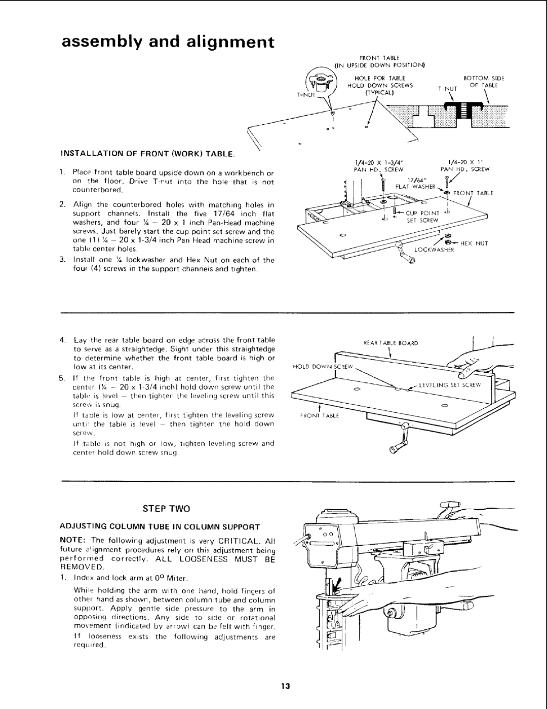
INSTALLATION OF FRONT (WORK) TABLE.
Place front table board upside down on a workbench or on the floor. Drive
2. Align the counterbored holes with matching holes in
support channels. Install the five 17/64 inch flat washers, and four 1/4- 20 x 1 inch
3.Install one ¼ Iockwasher and Hex Nut on each of the four (4) screws in the support channels and tighten.
Lay the rear table board on edge across the front table
to serve as a straightedge. Sight under this straightedge
to determine whether the front table board is high or low at its center.
5.If the front table is high at center, first tighten the center (Y, - 20 x
table is level then tighten the leveling screw until this screw is snug.
If table is low at center, first tighten the leveling screw unti the table is level - then tighten the hold down
scre_.
If table is not h_gh or low, tighten leveling screw and center hold down screw snug.
FRONT TABLE |
|
i/__._INUPSIDE DOWN POSITION) |
|
(_G_ / HOLE FOR TABLE | BOTTOM SIDE |
"O'hT O, L';REWS, .0, \ABLE | |
° | ° | 2 |
|
|
|
PAN | HD. | SCREW | PA_ | HD. | SCREW |
|
| 1' FLAT17/64"WASHER |
|
| |
|
|
| "_? | FRONT | TABLE |
|
|
| E |
|
|
NUT
LOCKWASHER
REAR TAiLE BOARD
HOLD DOW'N _= | J_ |
FRONT tABLE
STEP TWO
ADJUSTING COLUMN TUBE IN COLUMN SUPPORT
NOTE: The following adjustment is very CRITICAL. Al!
future alignment procedures rely on this adjustment being
performed correctly. ALL LOOSENESS MUST BE REMOVED.
t.Indux and lock arm at 0 ° Miter.
Whi!e holding the arm with one hand, hold fingers of other hand as shown, between column tube and column
support. Apply gentle side pressure to the arm in
opposing directions. Any side to side or rotational
movement (indicated by arrow) can be felt with finger.
If looseness exists the following adjustments are requi red,
13