2.Afler coolingto a safeoperatingtemperature,the overloadprotectorcanbeclosedmanuallybypushing in theredbuttonon thetopof themotor.If thered b_ttonwillnotsnapintoplaceimmediately,themotor isstilltoohotandmustbeallowedtocootforawhile
3, As soonasthe red buttonwill snapinto running position, the saw may be startedand operated
normally, by pulling out the saw switch to the "'ON" position.
4.Frequent opening of fuses or circuit breakers may result
if motor is overloaded, or if the motor circuit is fused
differently from recommendations, Overloading can occur if you feed to rapidly or if your saw is misaligned so that the blade heels. Do not use a fuse of greater capacity without consulting a qualified electrician.
5.Although the motor is designed for operation on the
voltage and frequency specified on motor nameplate, normal loads will be handled safely on voltages not more than 10% above or below the nameplate voltage.
Heavy loads, however, require that voltage at motor terminals equals the voltage specified on nameplate.
6.Most motor troubles may be traced to loose or
incorrect connections, overloading, reduced input
voltage (such as small size wires in the supply circuit) or
to an
connections, the load and the supply circuit, whenever
the motor fails to perform satisfactorily. Check wire sizes and lengths with the table following.
WIRE SIZES
The use of any extension cord will cause some loss of
power. To keep this to a minimum and to prevent
Use only 3 wire extension cords which have 3 prong grounding type plugs and
NOTE: For circuits of greater length, the wire size must be
increased proportionately in order to deliver ample voltage to the saw motor.
Wire Size Required
Length of the(American Wire Gauge Number)
Conductor240 Volt Lines 120 Volt Lines
Up to 100 feet | No. | 14 | No. | 12 | |||
100 feet | to | 200 | feet | No. | 12 | No. | 8 |
200 feet | to | 400 | feet | No. | 8 | No. | 6 |
3
SWIVEL
LATCH LEVER
[ABL CLAMP
\
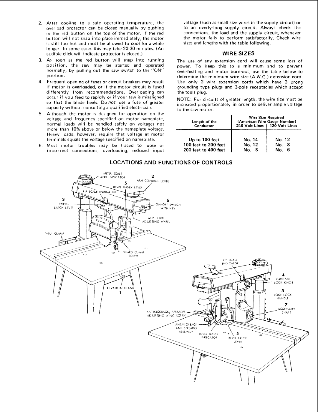
LOCATIONS AND FUNCTIONS OF CONTROLS
6
SWITCH
WITH KEY
RIP SCALE
INDICATOR
3
LOCK
HANDLE
7
ACCESSORY
SHAFT