assembly and alignment
3.To correct "heel" condition proceed as follows:
a.Remove left hand carriage cover.
b.Loosen the yoke clamp handle.
c.Loosen (slightly) the two
d Rotate the yoke assembly until gap between the saw blade and square is eliminated.
e. Lock yoke clamp handle and retighten the two he× head screws.
f, Recheck for "heel" and install carriage cover. g Loosen carriage lock knob.
NOTE: This alignment procedure will simultaneously set both yoke index ng positions for blade in and out rip.
HEX HEAD SCREWS
LEFT SIDE OF CARRIAGE
, ! I1k
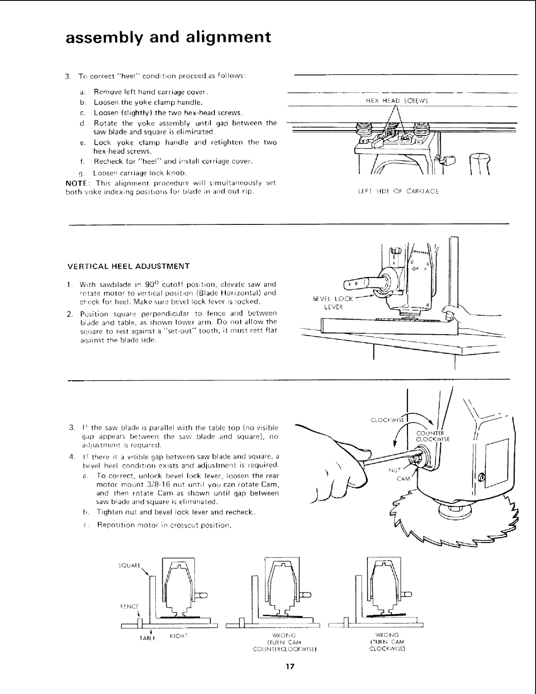
VERTICAL HEEL ADJUSTMENT
1.WiEh sawblade in 90 ° cutoff position, elevate saw and
rotate motor to vertical position (Blade Horizontal) and
c_eck | for heel. Make sure bevel | lock | lever | is locked. | BEVEL,lOCKf | " | I | ol | ||||
2. P_ssition square perpendicular | to | fence | and | between |
|
|
| |||||
blade | and | table, | as shown lower | am1. | Do | not | allow | the |
|
|
| |
square | to | rest against a | tooth, | it | must | rest | flat |
|
|
| ||
against | the | blade | side. |
|
|
|
|
|
|
|
|
|
CLOC
If the saw blade is parallel with t!le table top {no visible g,]p appears between the saw blade and square), no adjustment is requir_:d.
4.I_ there is a visible gap between saw blade and square, a
bevel heel condition exists and adjustment is required.
a.To correct, unlock bevel lock lever, loosen the rear motor mount
b.Tighten nut and bevel lock lever and recheck.
c.Reposition motor in crosscut position.
SQUARE
_E_c_NII _q_,
r_[] | / |
| _1 n |
| TABLE | RIGHT | WRONG |
|
| ||
|
|
| (TURN CAM |
|
|
| COUNTERCLOCKWISE} |
1
J
'/TR0 N G
(TUR Iq CAM
CLOCKed1SE}
17