STEP SIX
1. INSTALLINGAND ADJUSTING RIP SCALE INDICATORS.
NOTE: The rip scales and pointers are intended to
be used for quick settings. For greater accuracy,
take direct measurement between blade and fence.
a.
carriage cover.
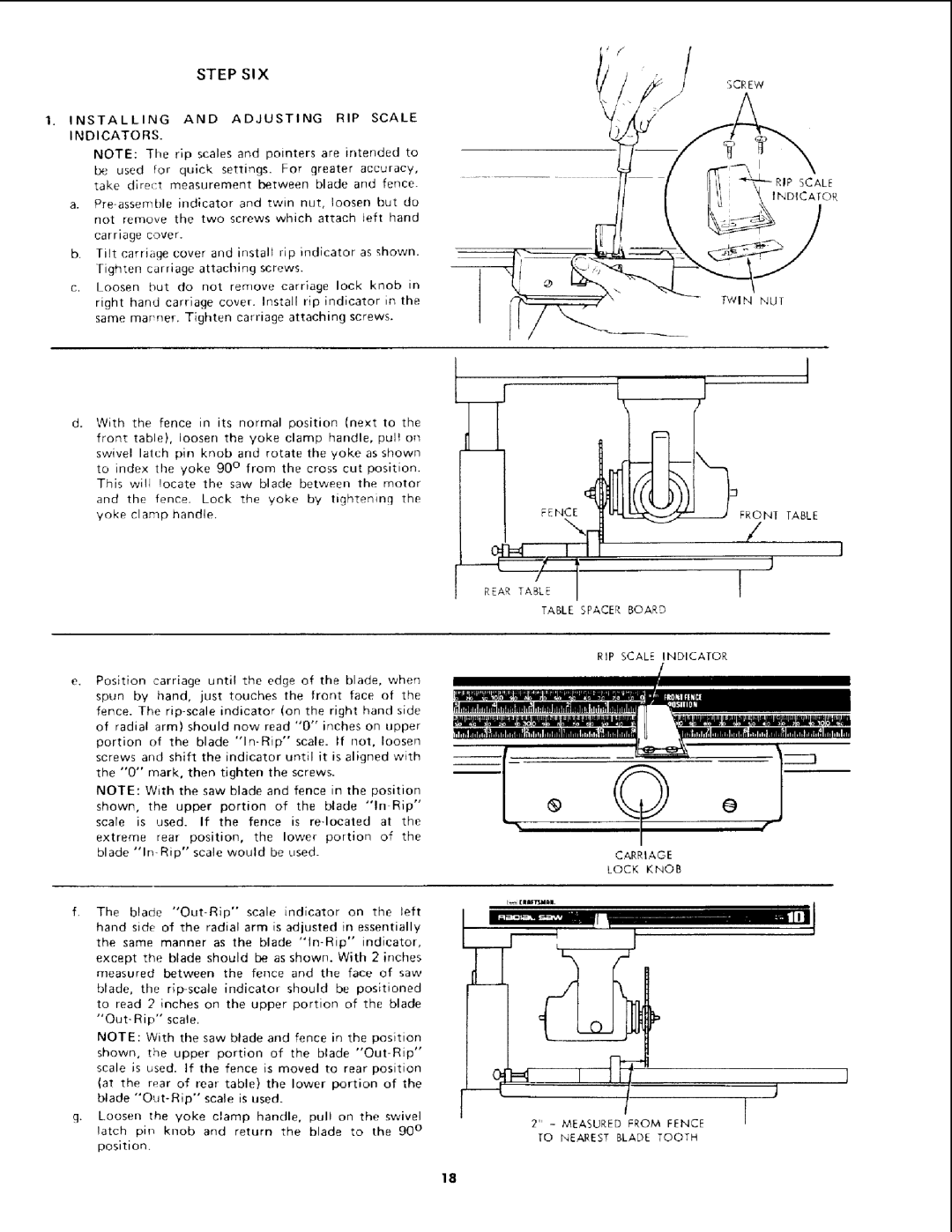
b.Tilt carriage cover and install rip indicator as shown. Tighten carriage attaching screws.
c.Loosen hut do not remove carriage lock knob in right hand carriage cover. Install rip indicator in the same mar ner. Tighten carriage attaching screws.
SCREW
TWIN NUT
k | i | i | I |
With the fence in its normal position (next to the front table), loosen the yoke clamp handle, pult on swivel latch pin knob and rotate the yoke as shown to index the yoke 90 ° from the cross cut position.
This will !ocate the saw blade between the motor
and the fence. Lock the yoke by tightening the yoke clamp handle.
Position carriage until the edge of the blade, when spun by hand, just touches the front face of the fence. The
portion of the blade
NOTE: With the saw blade and fence in the position
shown, the upper portion of the blade "In Rip"
scale is used. If the fence is
extreme rear position, the lower portion of the
blade
f. | The blade |
| scale | indicator | on | the | left | ||||
| hand side of the radial arm is adjusted in essentially | ||||||||||
| the same manner as the blade | ||||||||||
| except the blade should be as shown. With 2 inches | ||||||||||
| measured | between | the |
| fence | and the | face | of | saw | ||
| blade, | the | indicator | should | be positioned | ||||||
| to read 2 inches on the upper portion of the blade | ||||||||||
| scale. |
|
|
|
|
|
|
|
| ||
| NOTE: | With the saw blade and fence in the position | |||||||||
| shown, | the upper | portion | of the blade | |||||||
| scale is used. If the fence is moved to rear position | ||||||||||
| (at the rear of rear table) the lower portion of the | ||||||||||
| blade |
| scale | is used. |
|
|
|
| |||
g.Loosen the yoke clamp handle, pull on the swivel latch pin knob and return the blade to the 90 °
position.
I
TABLE SPACER BOARD
RIP SCALE INDICATOR
. | ® | O | er] |
|
| CARRIAGE | |
|
| LOCK | KNOB |
1
I
2" - MEASURED FROM FENCE
TO NEAREST BLADE TOOTH
18