SETTING UP THE STAND
(Fig. D, E, F)
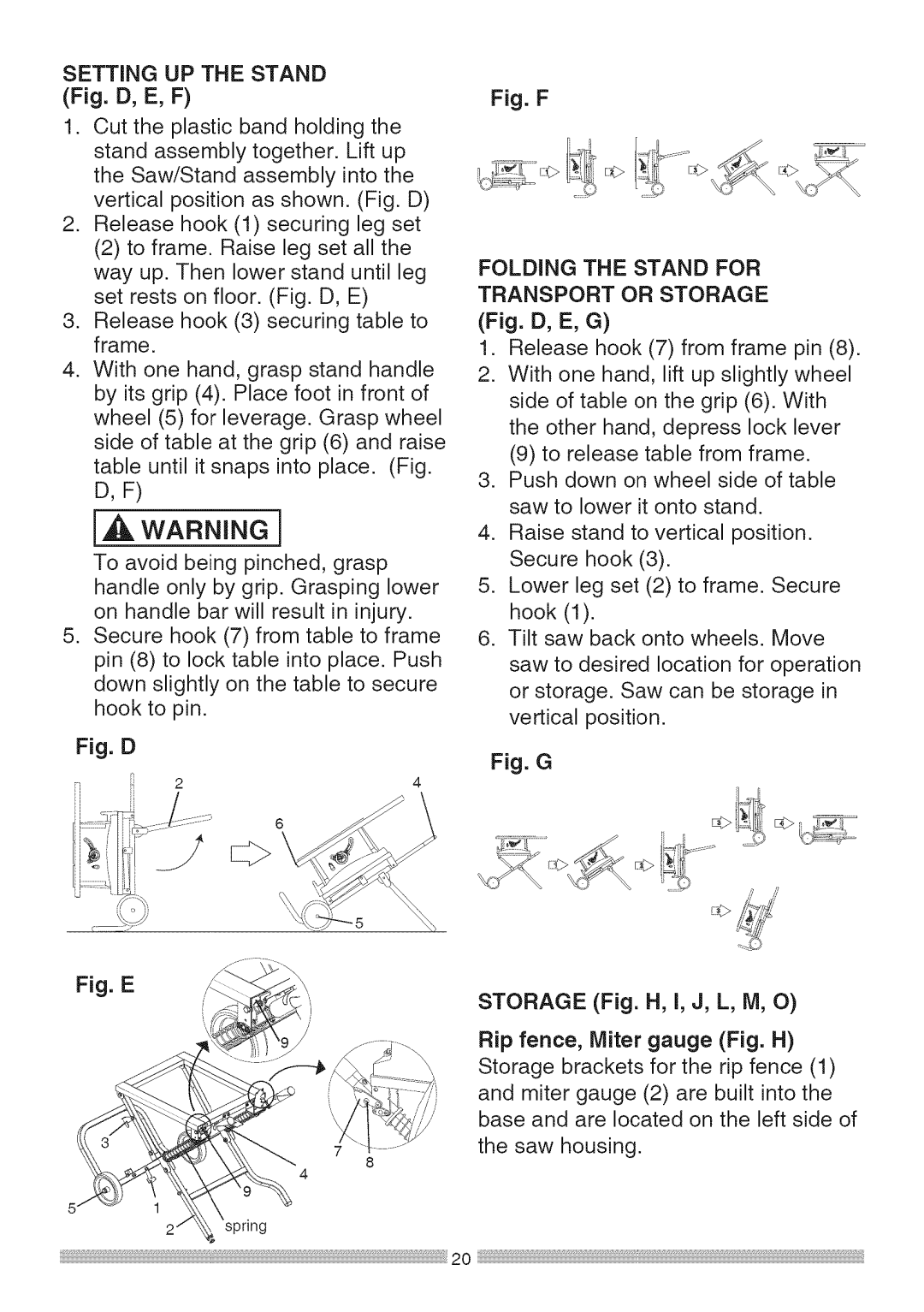
1.Cut the plastic band holding the stand assembly together. Lift up the Saw/Stand assembly into the vertical position as shown. (Fig. D)
2.Release hook (1) securing leg set
(2)to frame. Raise leg set all the way up. Then lower stand until leg set rests on floor. (Fig. D, E)
3.Release hook (3) securing table to frame.
4.With one hand, grasp stand handle by its grip (4). Place foot in front of wheel (5) for leverage. Grasp wheel side of table at the grip (6) and raise table until it snaps into place. (Fig.
D, F)
[,,_ WARNING I
To avoid being pinched, grasp handle only by grip. Grasping lower on handle bar will result in injury.
5.Secure hook (7) from table to frame pin (8) to lock table into place. Push down slightly on the table to secure hook to pin.
Fig. D
i] 2
_9 .....
Fig. E
Fig. F
_i_
FOLDING THE STAND FOR TRANSPORT OR STORAGE (Fig. D, E, G)
1.Release hook (7) from frame pin (8).
2.With one hand, lift up slightly wheel side of table on the grip (6). With the other hand, depress lock lever
(9)to release table from frame.
3.Push down on wheel side of table saw to lower it onto stand.
4.Raise stand to vertical position. Secure hook (3).
5.Lower leg set (2) to frame. Secure hook (1).
6.Tilt saw back onto wheels. Move saw to desired location for operation or storage. Saw can be storage in vertical position.
Fig. G
/
STORAGE (Fig. H, I, J, L, M, O)
Rip fence, Miter gauge (Fig. H) Storage brackets for the rip fence (1) and miter gauge (2) are built into the base and are located on the left side of the saw housing.
8
4
spring