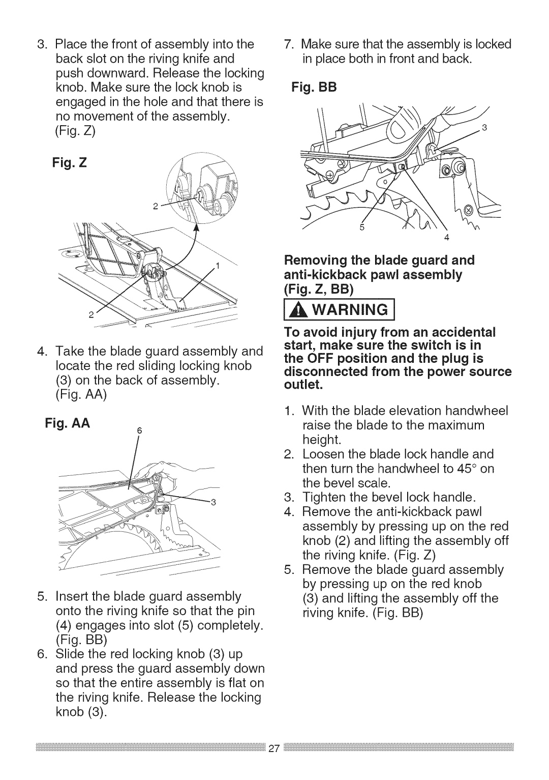
. Place the front of assembly into the back slot on the riving knife and
push downward. Release the locking knob. Make sure the lock knob is
engaged in the hole and that there is no movement of the assembly.
(Fig. Z)
Fig. Z
. Take the blade guard assembly and locate the red sliding locking knob
(3)on the back of assembly. (Fig. AA)
Fig. AA
6
5.Insert the blade guard assembly onto the riving knife so that the pin
(4)engages into slot (5) completely. (Fig. BB)
6.Slide the red locking knob (3) up and press the guard assembly down so that the entire assembly is flat on the riving knife. Release the locking knob (3).
7.Make sure that the assembly is locked in place both in front and back.
Fig. BB
5
4
Removing the blade guard and
I,,_ WARNING]
To avoid injury from an accidental start, make sure the switch is in the OFF position and the plug is
disconnected from the power source outlet.
1.With the blade elevation handwheel raise the blade to the maximum height.
2.Loosen the blade lock handle and then turn the handwheel to 45° on the bevel scale.
3.Tighten the bevel lock handle.
4.Remove the
5.Remove the blade guard assembly by pressing up on the red knob
(3)and lifting the assembly off the riving knife. (Fig. BB)
27
