i_ WARNING ]
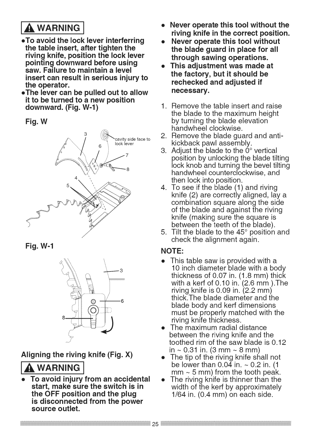
oTo avoid the lock lever interferring the table insert, after tighten the riving knife, position the lock lever pointing downward before using saw. Failure to maintain a level insert can result in serious injury to the operator.
oThe lever can be pulled out to allow it to be turned to a new position downward. (Fig.
Fig. W
J
Fig. W-1
Aligning the riving knife (Fig. X)
[_ WARNING]
o To avoid injury from an accidental start, make sure the switch is in
the OFF position and the plug
is disconnected from the power source outlet.
o Never operate this tool without the riving knife in the correct position.
oNever operate this tool without the blade guard in place for all through sawing operations.
o This adjustment was made at the factory, but it should be rechecked and adjusted if necessary.
1.Remove the table insert and raise the blade to the maximum height by turning the blade elevation handwheel clockwise.
2.Remove the blade guard and anti- kickback pawl assembly.
3.Adjust the blade to the 0° vertical position by unlocking the blade tilting lock knob and turning the bevel tilting handwheel counterclockwise, and then lock into position.
4.To see if the blade (1) and riving knife (2) are correctly aligned, lay a combination square along the side of the blade and against the riving knife (making sure the square is between the teeth of the blade).
5.Tilt the blade to the 45° position and check the alignment again.
NOTE:
oThis table saw is provided with a 10 inch diameter blade with a body thickness of 0.07 in. (1.8 mm) thick
with a kerf of 0.10 in. (2.6 mm ).The riving knife is 0.09 in. (2.2 mm) thick.The blade diameter and the
blade body and kerf dimensions must be properly matched with the riving knife thickness.
o The maximum radial distance
between the riving knife and the toothed rim of the saw blade is 0.12
in - 0.31 in. (3 mm - 8 mm)
oThe tip of the riving knife shall not be lower than 0.04 in. _ 0.2 in. (1 mm _ 5 mm) from the tooth peak.
oThe riving knife is thinner than the width of the kerf by approximately 1/64 in. (0.4 mm) on each side.
