Fig.N | b ) and the. locking.handle (6) to the | |
ottom ot the set plate (4). |
| |
|
| |
| Fig. K | 2 |
| Front |
|
Push stick (Fig. I, J)
Attach the metal
on the right side of the body shell.
The bracket will snap down into place. Place the push stick (3) into the bracket as shown in Fig. J.
Blade wrenches (Fig. J)
Insert the two blade wrenches into the slot (4) located on the right side of the saw housing, under the push stick.
Fig. J
4
1c_-_...._6
Storage for the
1.Take the
Fig. L
6
4
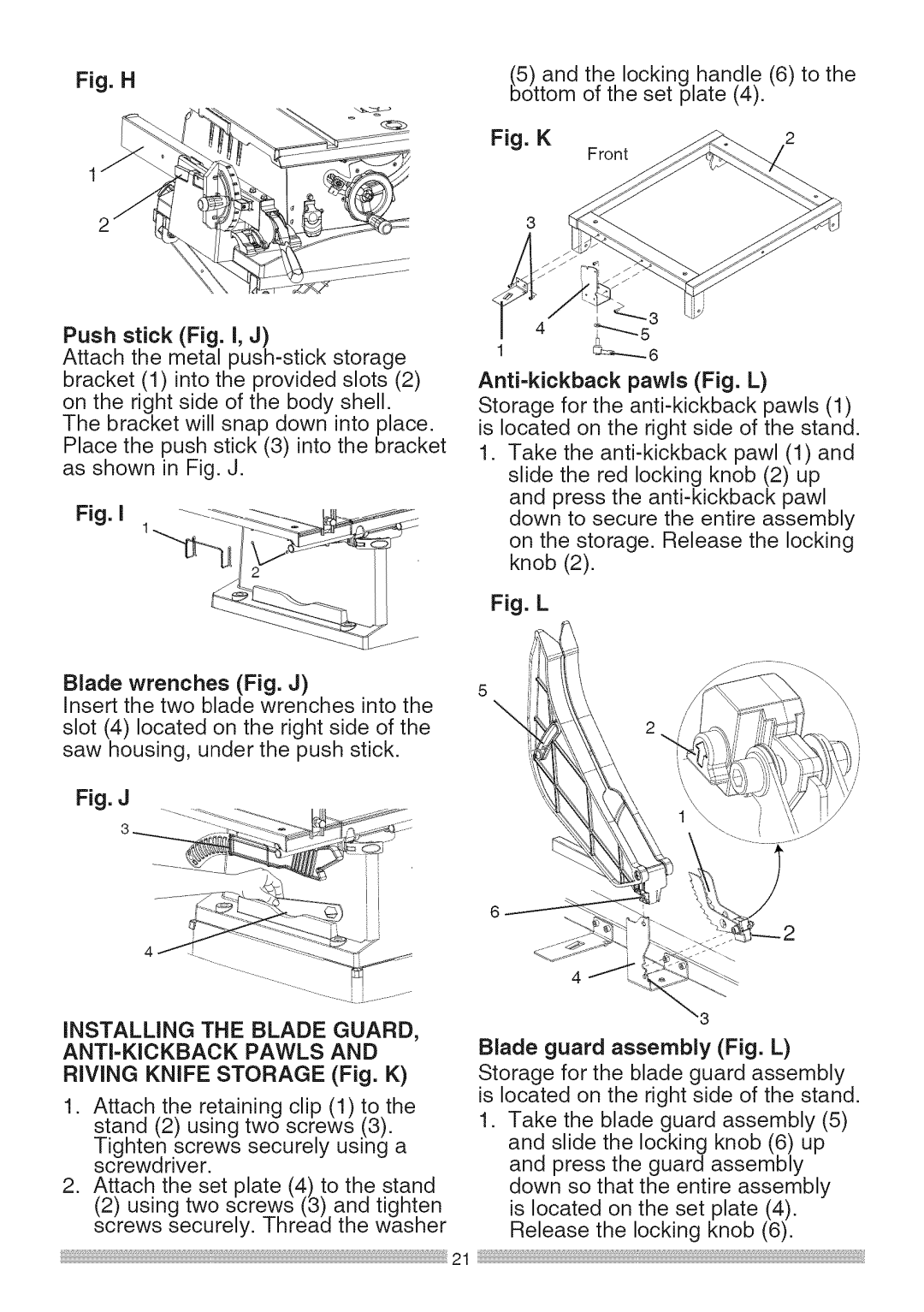
INSTALLING THE BLADE GUARD,
ANTI-KICKBACK PAWLS AND
RIVING KNIFE STORAGE (Fig. K)
1.Attach the retaining clip (1) to the stand (2) using two screws .(3).
Tighten .screws securely using a screwarwer.
2.Attach the set plate (4) to the stand
(2)using two screws (3) and tighten screws securely. Thread the washer
Blade guard assembly (Fig. L) Storage for the blade guard assembly is located on the right side of the stand.
1.Take the blade guard assembly (5)
and slide the locking knob (6) up and press the guard assembly down so that the entire assembly
is located on the set plate (4). Release the locking knob (6).