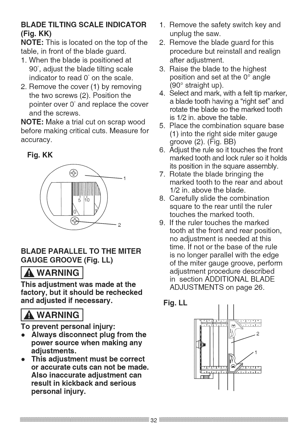
BLADETiLTiNG SCALE iNDiCATOR
(Fig. KK)
NOTE: This is located on the top of the table, in front of the blade guard.
1.When the blade is positioned at 90°, adjust the blade tilting scale indicator to read 0°on the scale.
2.Remove the cover (1) by removing the two screws (2). Position the pointer over 0°and replace the cover and the screws.
NOTE: Make a trial cut on scrap wood before making critical cuts. Measure for accuracy.
Fig. KK
BLADE PARALLEL TO THE MITER GAUGE GROOVE (Fig. LL)
[_, WARNING]
This adjustment was made at the factory, but it should be rechecked and adjusted if necessary.
[,A WARNING]
To prevent personal injury:
o Always disconnect plug from the
power source when making any adjustments.
o This adjustment must be correct or accurate cuts can not be made.
Also inaccurate adjustment can result in kickback and serious
personal injury.
1.Remove the safety switch key and unplug the saw.
2.Remove the blade guard for this procedure but reinstall and realign after adjustment.
3.Raise the blade to the highest position and set at the 0° angle (90 ° straight up).
4.Select and mark, with a felt tip marker, a blade tooth having a "right set" and rotate the blade so the marked tooth is 1/2 in. above the table.
5.Place the combination square base
(1)into the right side miter gauge groove (2). (Fig. BB)
6.Adjust the rule so it touches the front marked tooth and lock ruler so it holds
its position in the square assembly.
7.Rotate the blade bringing the marked tooth to the rear and about 1/2 in. above the blade.
8.Carefully slide the combination square to the rear until the ruler touches the marked tooth.
9.If the ruler touches the marked tooth at the front and rear position,
no adjustment is needed at this time. If not or the base of the rule
is no longer parallel with the edge of the miter gauge groove, perform
adjustment procedure described in section ADDITIONAL BLADE
ADJUSTMENTS on page 26.
Fig. LL
32