11. ACCELERATOR & BRAKE
Before starting to work, ensure that the Power SW is OFF. Failure to observe this can cause electric shock or short circuit.
Use care so as not to damage wirings. Damaged wiring can cause electric shock or short circuit.
Do not touch undesignated places. Touching places not designated can cause electric shock or short circuit.
This work should be performed by the Location's Maintenance Man or Serviceman. Performing work by
When performing work such as parts replacement other than those specified in this manual, be sure to contact where you purchased the product from. Confirm the work procedures and obtain precautions from where you purchased the product from prior to performing work. Inappropriate parts replacement and/or installation with erroneous adjustment can cause an overload or the parts to come into contact, resulting in an electric shock, a short circuit, and a fire.
If Accel. and Brake operation is not satisfactory, adjustment of Volume installation position or Volume replacement is needed. Also, be sure to apply greasing to the gear mesh portion once every 3 months.
11 - 1 ADJUSTING AND REPLACING THE V.R.
The appropriate value for both ACCEL. Volume and Brake Volume is under 30H when released and over C0H when stepped on. Check Volume values in the TEST mode. Since work is performed inside the energized cabinet, be very careful so as not to touch undesignated places. Touching places not specified can cause electric shock or short circuit.
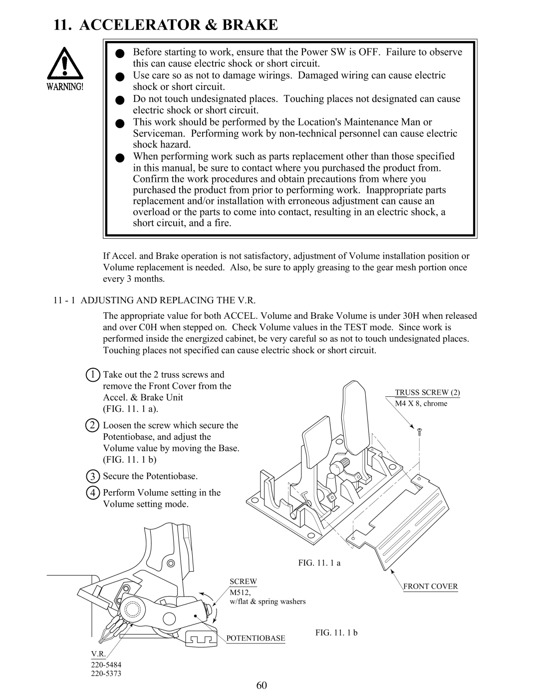
1Take out the 2 truss screws and remove the Front Cover from the Accel. & Brake Unit
(FIG. 11. 1 a).
2Loosen the screw which secure the Potentiobase, and adjust the Volume value by moving the Base. (FIG. 11. 1 b)
3Secure the Potentiobase.
4Perform Volume setting in the Volume setting mode.
TRUSS SCREW (2)
M4 X 8, chrome
FIG. 11. 1 a
SCREW
M512,
FRONT COVER
w/flat & spring washers
POTENTIOBASE
V.R.
FIG. 11. 1 b
60