computer, either PROJ1/CPU, PR0J2/CPU, or BOTH). If needed, you can also use the Switcher to output sound from a computer.
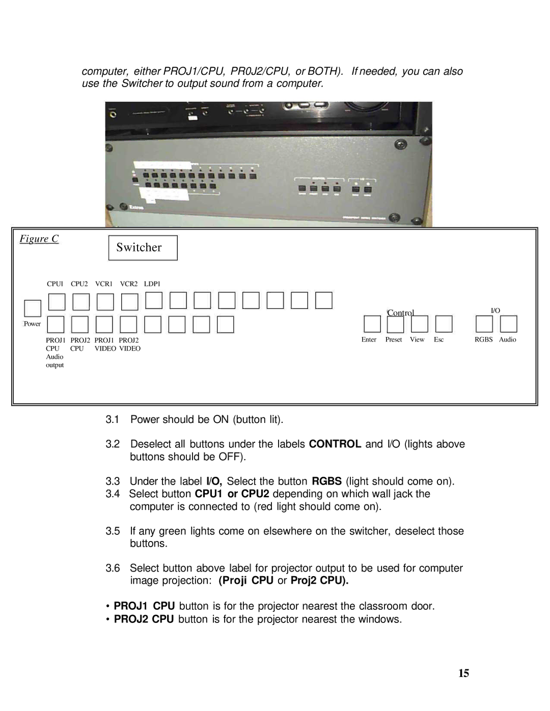
Figure C
Switcher
CPUl CPU2 VCR1 VCR2 LDP1
|
|
| Control | I/O |
Power |
|
|
|
|
PROJ1 | PROJ2 | PROJ1 PROJ2 | Enter Preset View Esc | RGBS Audio |
CPU | CPU | VIDEO VIDEO |
|
|
Audio |
|
|
|
|
output |
|
|
|
|
3.1Power should be ON (button lit).
3.2Deselect all buttons under the labels CONTROL and I/O (lights above buttons should be OFF).
3.3Under the label I/O, Select the button RGBS (light should come on).
3.4Select button CPU1 or CPU2 depending on which wall jack the computer is connected to (red light should come on).
3.5If any green lights come on elsewhere on the switcher, deselect those buttons.
3.6Select button above label for projector output to be used for computer image projection: (Proji CPU or Proj2 CPU).
•PROJ1 CPU button is for the projector nearest the classroom door.
•PROJ2 CPU button is for the projector nearest the windows.
15