MZ-N10
SECTION 5
ELECTRICAL ADJUSTMENTS
Outline
•In this set, automatic adjustment of CD and MO can be per- formed by entering the test mode.
However, before starting automatic adjustment, the memory clear, power supply adjustment, and laser power check must be performed in the manual mode.
•A key having no particular description in the text, indicates a set key.
•For the LCD display, the LCD on the remote commander is shown, but the contents of LCD display on the set are same.
NV Reset
Caution: The shipment data will be cleared without the adjusted values of the electrical offset adjustment and power sup- ply adjustment when the NV is reset.
• Setting method of NV reset
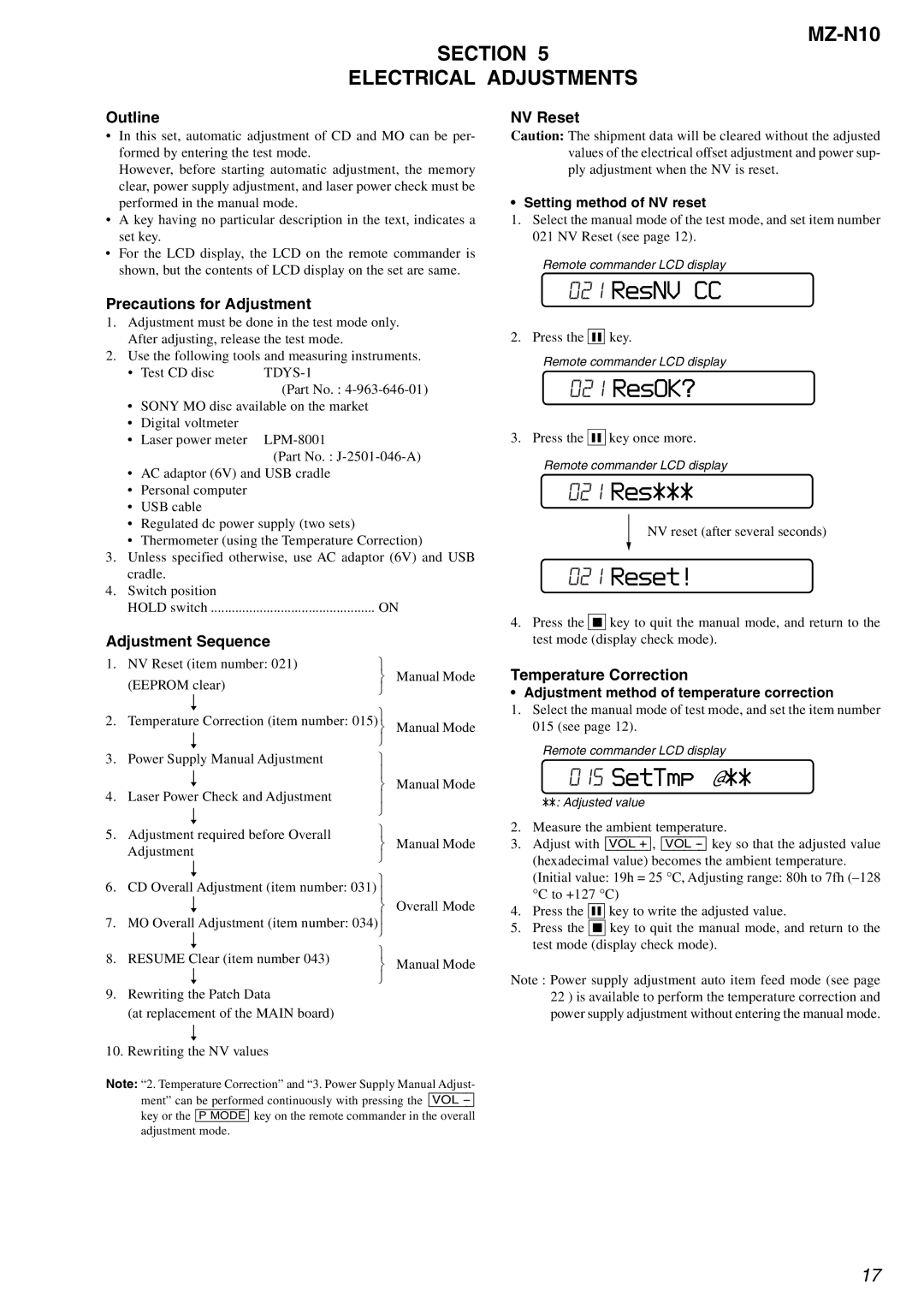
1.Select the manual mode of the test mode, and set item number 021 NV Reset (see page 12).
Remote commander LCD display
Precautions for Adjustment
1.Adjustment must be done in the test mode only. After adjusting, release the test mode.
2.Use the following tools and measuring instruments.
• Test CD disc |
|
| (Part No. : |
•SONY MO disc available on the market
•Digital voltmeter
• Laser power meter
(Part No. :
•AC adaptor (6V) and USB cradle
•Personal computer
•USB cable
•Regulated dc power supply (two sets)
•Thermometer (using the Temperature Correction)
3.Unless specified otherwise, use AC adaptor (6V) and USB cradle.
4.Switch position
HOLD switch ............................................... ON
Adjustment Sequence
1. | NV Reset (item number: 021) | |
| |
| (EEPROM clear) | | Manual Mode | |
| |
| ||
| r | |
| |
2. |
| Manual Mode | ||
Temperature Correction (item number: 015) | ||||
| r | |
| |
3. | Power Supply Manual Adjustment | |
| |
| r | | Manual Mode | |
| | |||
4. | Laser Power Check and Adjustment | |
| |
| r | |
| |
| |
| ||
5. | Adjustment required before Overall |
| ||
| Manual Mode | |||
| Adjustment | |||
| |
| ||
| r | |
| |
6. | CD Overall Adjustment (item number: 031) |
| ||
|
| |||
| r | | Overall Mode | |
7. |
| |
| |
MO Overall Adjustment (item number: 034) |
| |||
| r | |
| |
8. | RESUME Clear (item number 043) |
| ||
| Manual Mode | |||
| r | |||
| |
| ||
9.Rewriting the Patch Data
(at replacement of the MAIN board) r
10.Rewriting the NV values
Note: “2. Temperature Correction” and “3. Power Supply Manual Adjust-
ment” can be performed continuously with pressing the [VOL
021 ResNV CC
2. Press the X key.
Remote commander LCD display
021ResOK?
3.Press the X key once more.
Remote commander LCD display
021Res***
NV reset (after several seconds)
021Reset!
4.Press the x key to quit the manual mode, and return to the test mode (display check mode).
Temperature Correction
• Adjustment method of temperature correction
1.Select the manual mode of test mode, and set the item number 015 (see page 12).
Remote commander LCD display
015 SetTmp @**
**: Adjusted value
2.Measure the ambient temperature.
3.Adjust with [VOL +], [VOL
(hexadecimal value) becomes the ambient temperature. (Initial value: 19h = 25 °C, Adjusting range: 80h to 7fh
4.Press the X key to write the adjusted value.
5.Press the x key to quit the manual mode, and return to the test mode (display check mode).
Note : Power supply adjustment auto item feed mode (see page 22 ) is available to perform the temperature correction and power supply adjustment without entering the manual mode.
17