MZ-N10
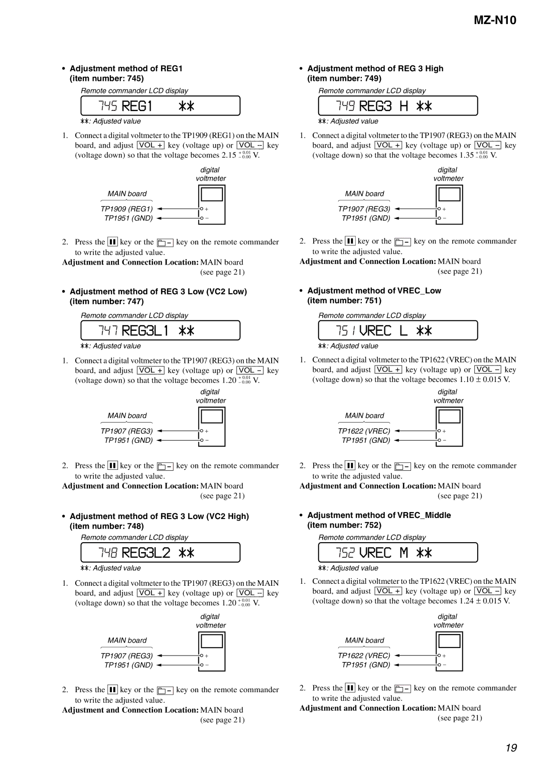
•Adjustment method of REG1 (item number: 745)
Remote commander LCD display
745 REG1 | ** |
**: Adjusted value |
|
1.Connect a digital voltmeter to the TP1909 (REG1) on the MAIN board, and adjust [VOL +] key (voltage up) or [VOL
digital voltmeter
MAIN board
TP1909 (REG1)
TP1951 (GND)
2. Press the X key or the ![]() key on the remote commander to write the adjusted value.
key on the remote commander to write the adjusted value.
Adjustment and Connection Location: MAIN board (see page 21)
•Adjustment method of REG 3 Low (VC2 Low) (item number: 747)
Remote commander LCD display
747 REG3L1 **
**: Adjusted value
1.Connect a digital voltmeter to the TP1907 (REG3) on the MAIN board, and adjust [VOL +] key (voltage up) or [VOL
digital voltmeter
MAIN board
TP1907 (REG3)
TP1951 (GND)
2. Press the X key or the ![]() key on the remote commander to write the adjusted value.
key on the remote commander to write the adjusted value.
Adjustment and Connection Location: MAIN board (see page 21)
•Adjustment method of REG 3 Low (VC2 High) (item number: 748)
Remote commander LCD display
748 REG3L2 **
**: Adjusted value
1.Connect a digital voltmeter to the TP1907 (REG3) on the MAIN board, and adjust [VOL +] key (voltage up) or [VOL
digital voltmeter
MAIN board
TP1907 (REG3)
TP1951 (GND)
2. Press the X key or the ![]() key on the remote commander to write the adjusted value.
key on the remote commander to write the adjusted value.
Adjustment and Connection Location: MAIN board (see page 21)
•Adjustment method of REG 3 High (item number: 749)
Remote commander LCD display
749 REG3 H **
**: Adjusted value
1.Connect a digital voltmeter to the TP1907 (REG3) on the MAIN board, and adjust [VOL +] key (voltage up) or [VOL
digital voltmeter
MAIN board
TP1907 (REG3)
TP1951 (GND)
2. Press the X key or the ![]() key on the remote commander to write the adjusted value.
key on the remote commander to write the adjusted value.
Adjustment and Connection Location: MAIN board (see page 21)
•Adjustment method of VREC_Low (item number: 751)
Remote commander LCD display
751 VREC L **
**: Adjusted value
1.Connect a digital voltmeter to the TP1622 (VREC) on the MAIN
board, and adjust [VOL +] key (voltage up) or [VOL
digital voltmeter
MAIN board
TP1622 (VREC)
TP1951 (GND)
2. Press the X key or the ![]() key on the remote commander to write the adjusted value.
key on the remote commander to write the adjusted value.
Adjustment and Connection Location: MAIN board (see page 21)
•Adjustment method of VREC_Middle (item number: 752)
Remote commander LCD display
752 VREC M **
**: Adjusted value
1.Connect a digital voltmeter to the TP1622 (VREC) on the MAIN
board, and adjust [VOL +] key (voltage up) or [VOL
digital voltmeter
MAIN board
TP1622 (VREC)
TP1951 (GND)
2. Press the X key or the ![]() key on the remote commander to write the adjusted value.
key on the remote commander to write the adjusted value.
Adjustment and Connection Location: MAIN board (see page 21)
19