Left Side/Rear
1 | 2 |
|
|
3 |
|
|
|
| 4 5 | 6 78 9 0 | qa |
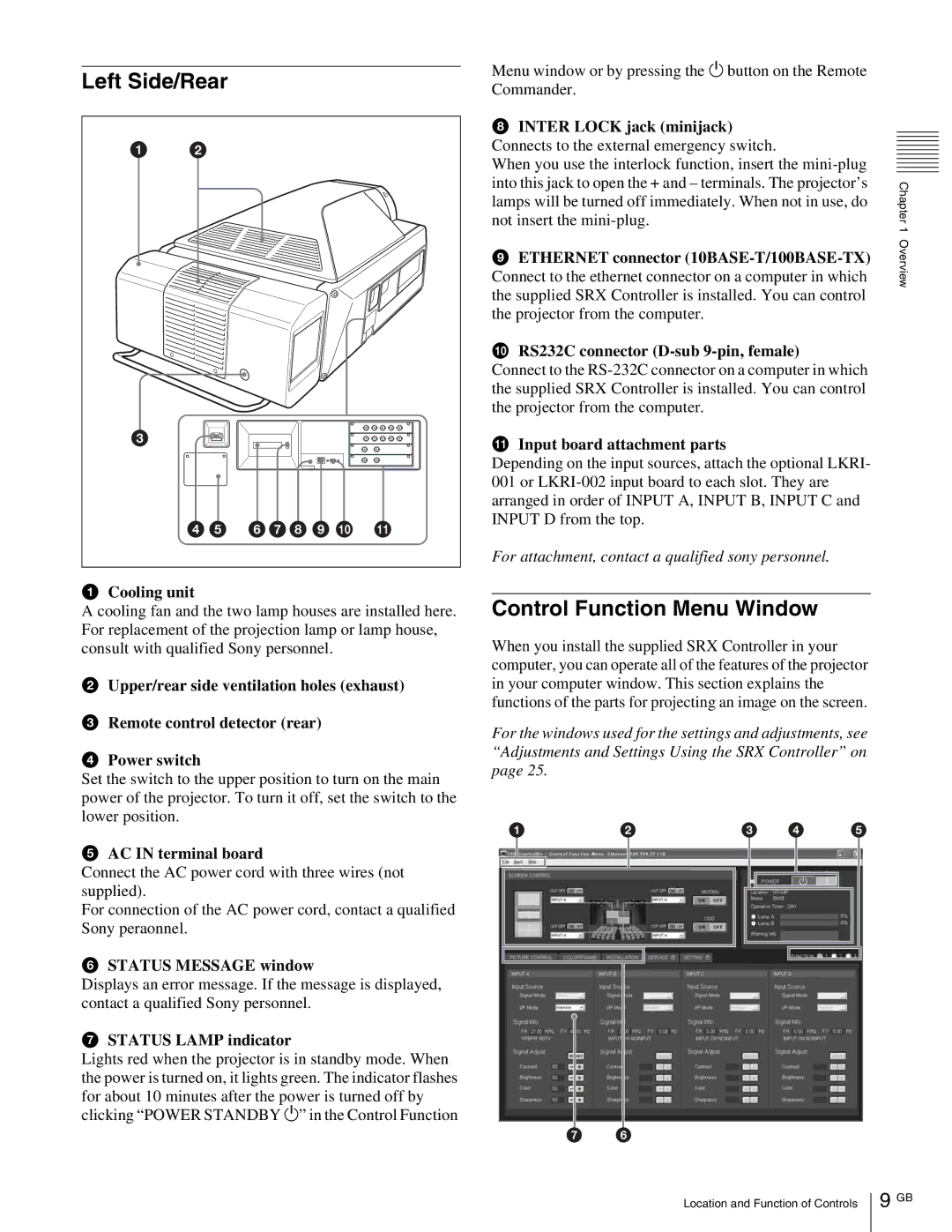
a Cooling unit |
|
| |
A cooling fan and the two lamp houses are installed here. For replacement of the projection lamp or lamp house, consult with qualified Sony personnel.
bUpper/rear side ventilation holes (exhaust)
cRemote control detector (rear)
dPower switch
Set the switch to the upper position to turn on the main power of the projector. To turn it off, set the switch to the lower position.
eAC IN terminal board
Connect the AC power cord with three wires (not supplied).
For connection of the AC power cord, contact a qualified Sony peraonnel.
fSTATUS MESSAGE window
Displays an error message. If the message is displayed, contact a qualified Sony personnel.
gSTATUS LAMP indicator
Lights red when the projector is in standby mode. When the power is turned on, it lights green. The indicator flashes for about 10 minutes after the power is turned off by clicking “POWER STANDBY 1” in the Control Function
Menu window or by pressing the 1 button on the Remote Commander.
hINTER LOCK jack (minijack) Connects to the external emergency switch.
When you use the interlock function, insert the
iETHERNET connector
jRS232C connector (D-sub 9-pin, female)
Connect to the
kInput board attachment parts
Depending on the input sources, attach the optional LKRI- 001 or
For attachment, contact a qualified sony personnel.
Control Function Menu Window
When you install the supplied SRX Controller in your computer, you can operate all of the features of the projector in your computer window. This section explains the functions of the parts for projecting an image on the screen.
For the windows used for the settings and adjustments, see “Adjustments and Settings Using the SRX Controller” on page 25.
1 | 2 | 3 | 4 | 5 | |||||||||
|
|
|
|
|
|
|
|
|
|
|
|
|
|
|
|
|
|
|
|
|
|
|
|
|
|
|
|
|
|
|
|
|
|
|
|
|
|
|
|
|
|
|
|
|
|
|
|
|
|
|
|
|
|
|
|
|
|
|
|
|
|
|
|
|
|
|
|
|
|
|
|
|
|
|
|
|
|
|
|
|
|
|
|
|
|
|
|
|
|
|
|
|
|
|
|
|
|
|
|
|
|
|
|
|
|
|
|
|
|
|
|
76 6
Chapter 1 Overview
Location and Function of Controls
9GB