Parallel Interface
Connector Signals
Pin |
|
|
|
|
| Name | Function | |||||
|
|
|
|
|
|
|
|
|
|
|
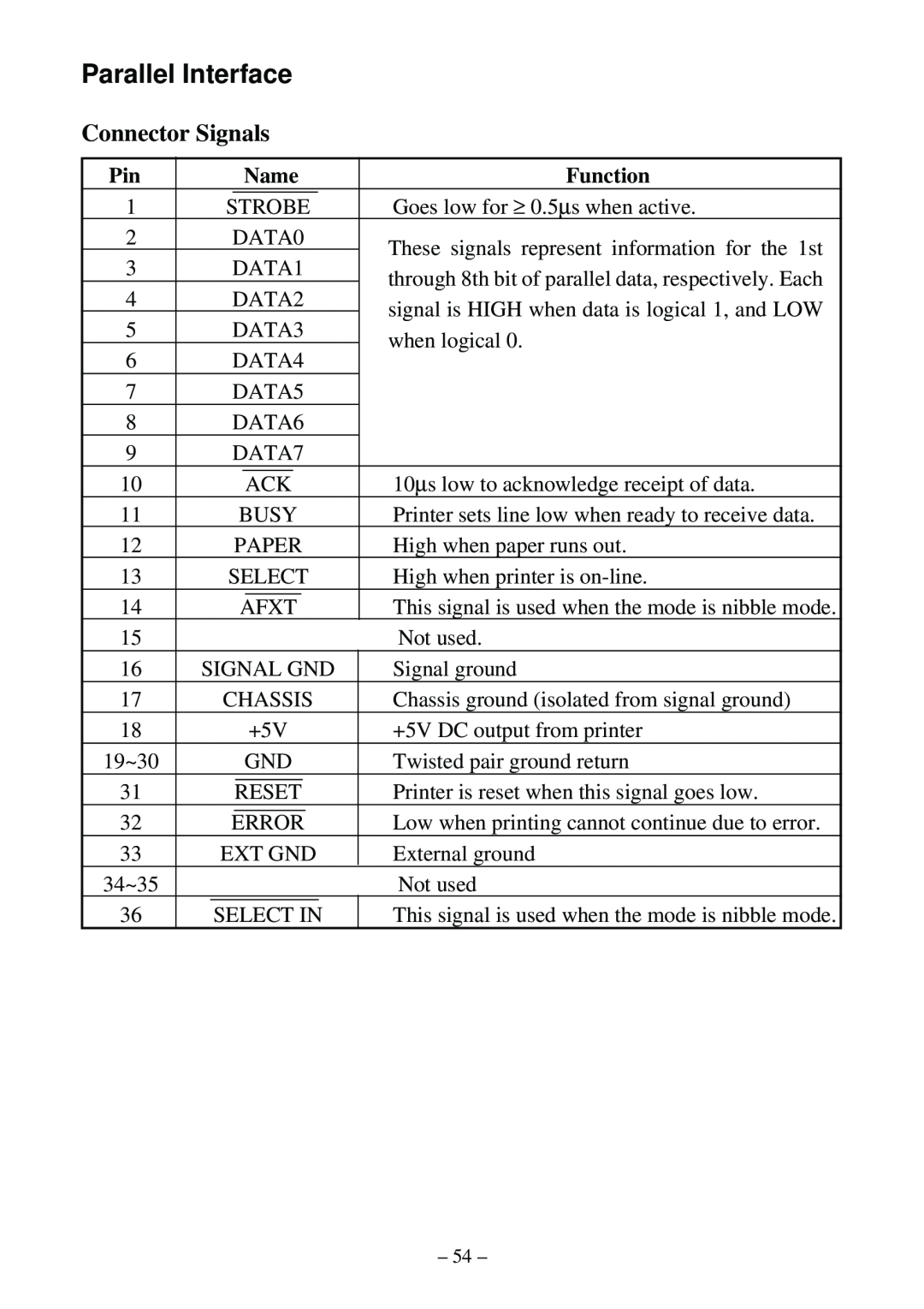
| Goes low for ≥ 0.5∝ s when active. |
1 |
| STROBE | ||||||||||
2 |
| DATA0 | These signals represent information for the 1st | |||||||||
3 |
| DATA1 | ||||||||||
| through 8th bit of parallel data, respectively. Each | |||||||||||
4 |
| DATA2 | ||||||||||
| signal is HIGH when data is logical 1, and LOW | |||||||||||
5 |
| DATA3 | ||||||||||
| when logical 0. | |||||||||||
6 |
| DATA4 | ||||||||||
|
| |||||||||||
7 |
| DATA5 |
| |||||||||
8 |
| DATA6 |
| |||||||||
9 |
| DATA7 |
| |||||||||
|
|
|
|
|
|
|
|
|
|
|
| 10∝ s low to acknowledge receipt of data. |
10 |
|
|
|
|
| ACK | ||||||
11 |
|
|
|
| BUSY | Printer sets line low when ready to receive data. | ||||||
12 |
|
| PAPER | High when paper runs out. | ||||||||
13 |
| SELECT | High when printer is | |||||||||
|
|
|
|
|
|
|
|
|
|
| ||
14 |
|
|
|
| AFXT | This signal is used when the mode is nibble mode. | ||||||
15 |
|
|
|
|
|
|
|
|
|
|
| Not used. |
16 | SIGNAL GND | Signal ground | ||||||||||
17 |
| CHASSIS | Chassis ground (isolated from signal ground) | |||||||||
18 |
|
|
|
|
|
| +5V | +5V DC output from printer | ||||
19~30 |
|
|
|
|
| GND | Twisted pair ground return | |||||
31 |
|
|
|
|
|
| Printer is reset when this signal goes low. | |||||
|
|
|
| RESET |
|
|
| |||||
32 |
|
|
| Low when printing cannot continue due to error. | ||||||||
|
| ERROR |
|
| ||||||||
33 |
| EXT GND | External ground | |||||||||
34~35 |
|
|
|
|
|
|
|
|
|
|
| Not used |
36 |
| SELECT IN | This signal is used when the mode is nibble mode. | |||||||||
– 54 –