LED DISPLAY CONSOLE INSTALLATION INSTRUCTIONS
Step 1.
Remove electronic display console from pack- aging materials.
Note: If you are installing an iPod® Kit, a MYE Entertain- ment kit or a Personal Viewing Screen kit along with this display, it is recommended that you install the kit’s center console before you mount the display onto the frame.
Step 2.
If the back display covers are attached to display console then remove and save them for later use, otherwise proceed to the next step.
|
|
|
|
|
|
|
|
|
|
|
| g |
|
|
|
|
|
|
|
|
|
|
|
|
|
|
|
| f |
|
|
|
| j |
|
| |
|
|
|
|
|
|
|
| e |
|
|
|
|
| |||||
|
|
|
|
|
|
|
|
|
|
| i |
|
|
| ||||
|
|
|
|
|
| d |
|
|
|
|
|
|
| |||||
|
| b |
|
| ||||||||||||||
|
|
|
|
|
|
| ||||||||||||
|
|
|
|
|
|
|
|
|
|
|
|
|
| |||||
a |
|
| c |
|
|
|
|
|
|
|
|
|
|
|
| h | ||
|
|
|
|
|
|
|
|
|
|
|
|
|
|
| ||||
|
|
|
|
|
|
|
|
|
|
|
|
|
|
|
| |||
|
|
|
|
|
|
|
|
|
|
|
|
|
|
|
|
|
| |
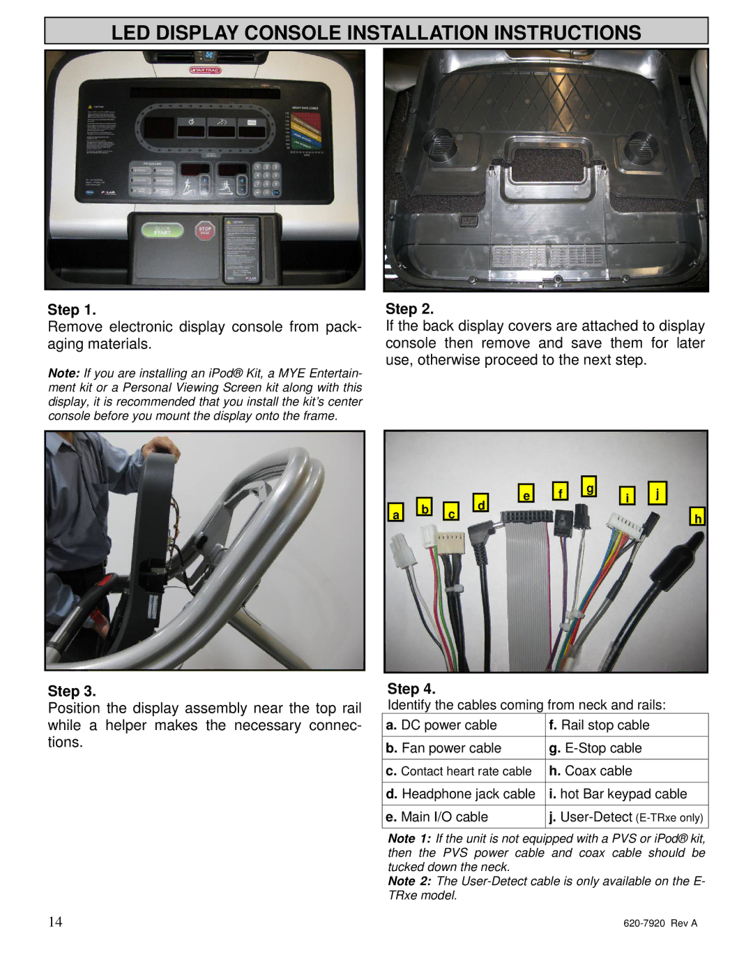
Step 3.
Position the display assembly near the top rail while a helper makes the necessary connec- tions.
Step 4.
Identify the cables coming from neck and rails:
a. DC power cable | f. Rail stop cable |
|
|
b. Fan power cable | g. |
|
|
c. Contact heart rate cable | h. Coax cable |
|
|
d. Headphone jack cable | i. hot Bar keypad cable |
|
|
e. Main I/O cable | j. |
|
|
Note 1: If the unit is not equipped with a PVS or iPod® kit, then the PVS power cable and coax cable should be tucked down the neck.
Note 2: The
14 |