I/O Interface
Screw Locations
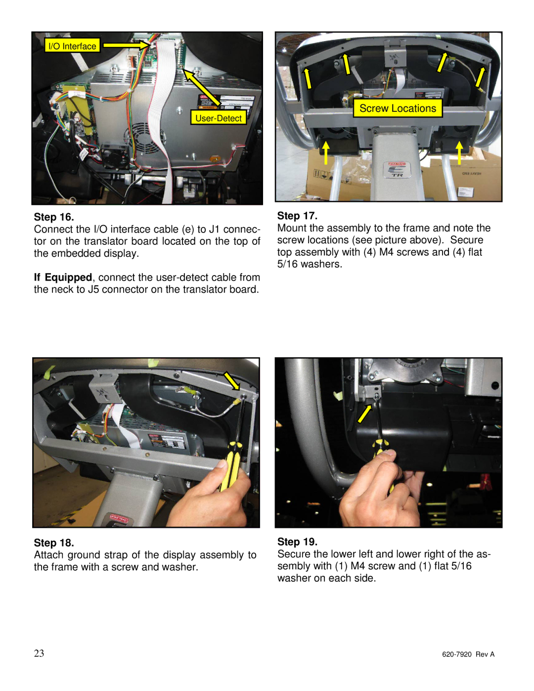
Step 16.
Connect the I/O interface cable (e) to J1 connec- tor on the translator board located on the top of the embedded display.
If Equipped, connect the
Step 18.
Attach ground strap of the display assembly to the frame with a screw and washer.
23
Step 17.
Mount the assembly to the frame and note the screw locations (see picture above). Secure top assembly with (4) M4 screws and (4) flat 5/16 washers.
Step 19.
Secure the lower left and lower right of the as- sembly with (1) M4 screw and (1) flat 5/16 washer on each side.