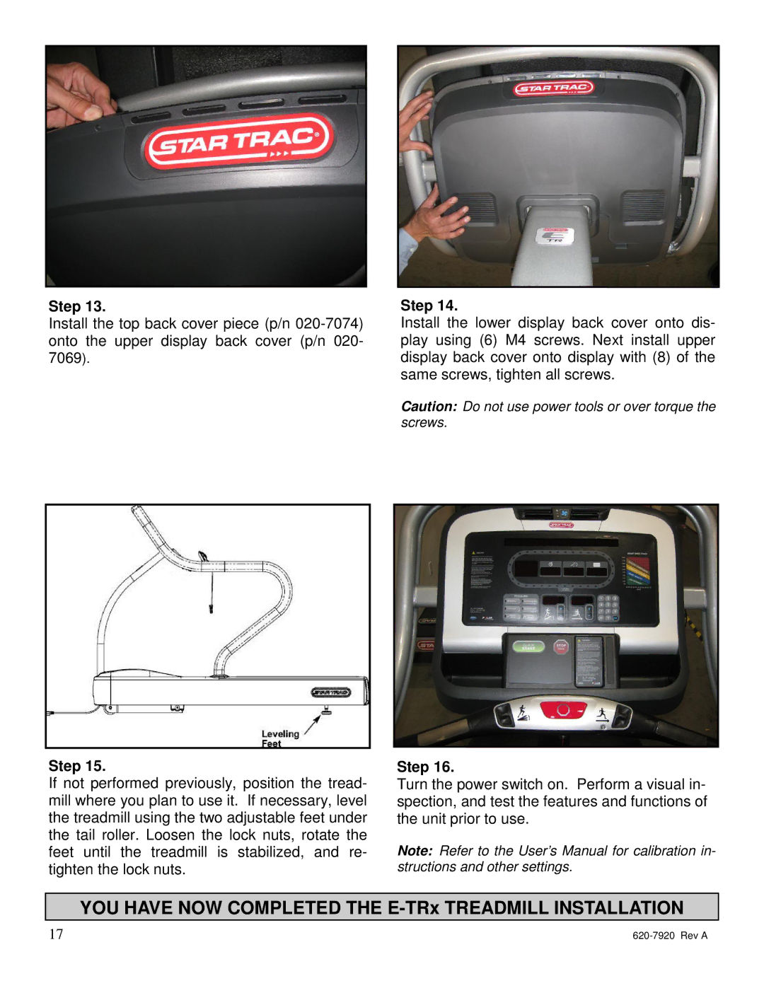
Step 13.
Install the top back cover piece (p/n
Step 15.
If not performed previously, position the tread- mill where you plan to use it. If necessary, level the treadmill using the two adjustable feet under the tail roller. Loosen the lock nuts, rotate the feet until the treadmill is stabilized, and re- tighten the lock nuts.
Step 14.
Install the lower display back cover onto dis- play using (6) M4 screws. Next install upper display back cover onto display with (8) of the same screws, tighten all screws.
Caution: Do not use power tools or over torque the screws.
Step 16.
Turn the power switch on. Perform a visual in- spection, and test the features and functions of the unit prior to use.
Note: Refer to the User’s Manual for calibration in- structions and other settings.
YOU HAVE NOW COMPLETED THE E-TRx TREADMILL INSTALLATION
17 |
