Star Trac Pro STM Treadmill manual Connecting the Display Cables

Models: Pro STM Treadmill

1 60
Download 60 pages 45.18 Kb
Page 17
Image 17

Position the bottom of each handrail over its associated mounting hole in the frame assembly. Insert one 5/16” x 7.5” screw, with a flat washer installed, through the bottom of the frame assembly, and thread into each handrail. Use 9 1/2” wrench to tighten the screws.

Step 5e

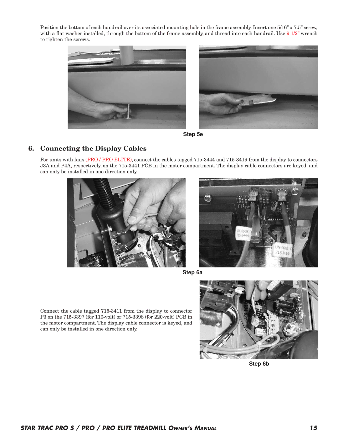
6. Connecting the Display Cables

For units with fans (PRO / PRO ELITE), connect the cables tagged 715-3444 and 715-3419 from the display to connectors J3A and P4A, respectively, on the 715-3441 PCB in the motor compartment. The display cable connectors are keyed, and can only be installed in one direction only.

Step 6a

Connect the cable tagged 715-3411 from the display to connector P3 on the 715-3397 (for 110-volt) or 715-3398 (for 220-volt) PCB in the motor compartment. The display cable connector is keyed, and can only be installed in one direction only.

Step 6b

STAR TRAC PRO S / PRO / PRO ELITE TREADMILL OWNERS MANUAL

15

Page 17
Image 17
Star Trac Pro STM Treadmill manual Connecting the Display Cables