Manuals
/
Sterling
/
Household Appliance
/
Plumbing Product
Sterling
BP1012, BP1018
installation manual
Typical Wiring Diagram
Models:
BP1012
BP1018
1
49
53
53
Download
53 pages
44.94 Kb
46
47
48
49
50
51
52
53
Troubleshooting
Specs
Install
Parts list
Typical Wiring Diagram
Warranty
Maintenance
Electrical Problems
Safety Procedures
Checklist
Page 49
Image 49
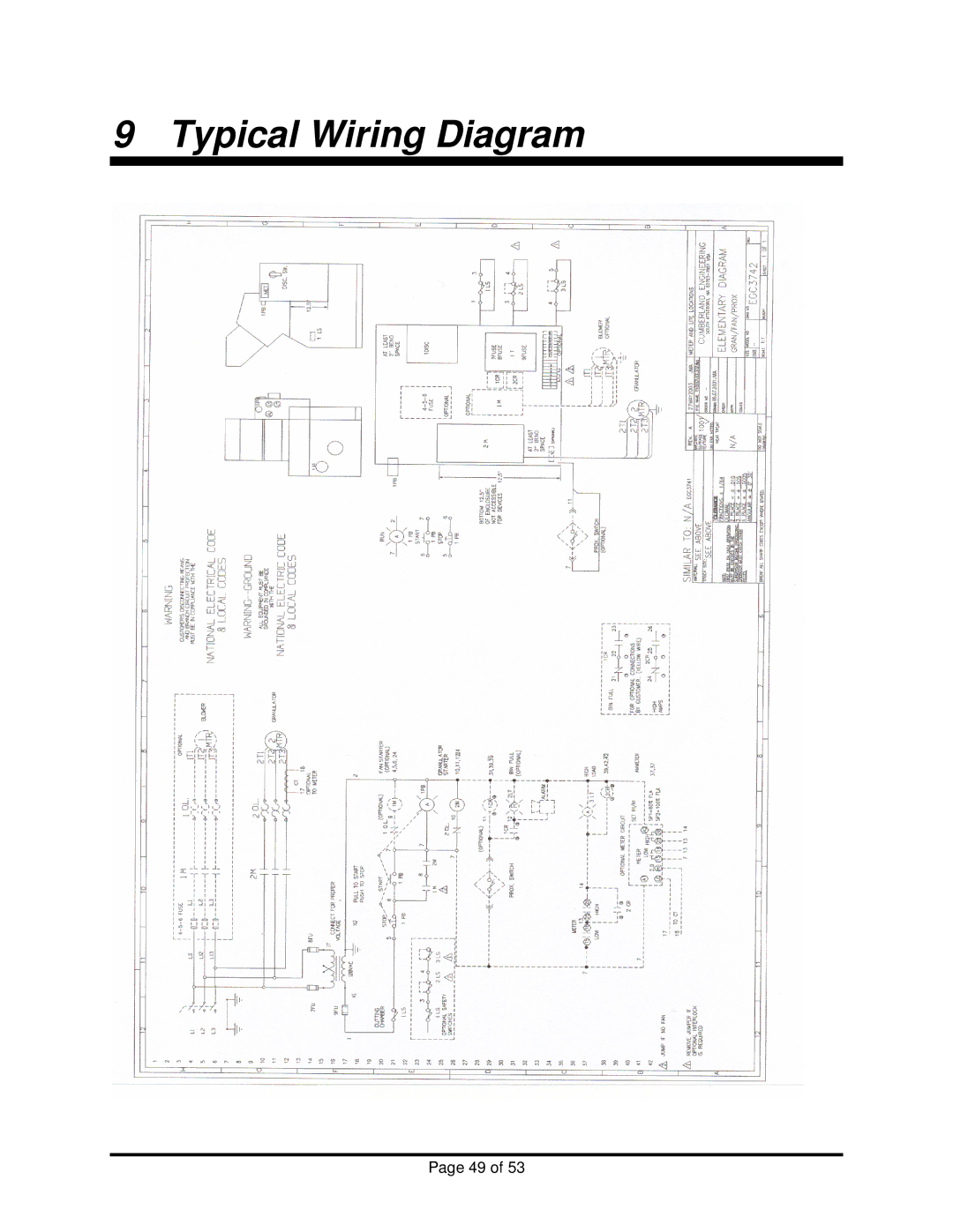
9 Typical Wiring Diagram
Page 49 of 53
Page 48
Page 50
Page 49
Image 49
Page 48
Page 50
Contents
BP1000 Series Granulators
Page
Sterling Warranty Information
Sterling Warranty Information
Table of Contents
Start Up and Operation
Table of Figures
Viii
Safety Guidelines
Safety Considerations
Page
Guidelines for Moving the Granulator
Safety Procedures
Clearing a Jammed Cutting Chamber
Safety Features Fitted On the Granulator
Safety Features
Opening the Granulator
Safety Switch
Sound Enclosure
Wear protective gloves when exposed to knives
Model Motor Power
Noise Test Method
General Information
Using This Manual
Introduction
Description
Safety Symbols Used in This Manual
Optional Equipment
Main Components of Standard Granulators
Model
Unpacking and Inspection
Shipping Information
Event of Shipping Damage
If the Shipment is Not Complete
Returns
If the Shipment is Not Correct
Uncrating Your Granulator
Especially the Hopper
Lifting
Installation
Positioning the Granulator
Inserting the Bin
Electrical Connection
Checking the Cutting Chamber
Start-Up Checks
Removing the Screw Knob
Checking Rotation Direction
Checking Knife Position
Test the Interlock Switches
Checking the Knife Gap
Start Up and Operation
Pre-Operational Checklist
Never push material into the hopper with hands
Operation
General Recommendations
Maintenance
Drive Belt Tension
Monthly Maintenance Operations
Proper Belt Tension
Belt Replacement
Removal and Replacement of the Screen
Removing the Screen
Inspection and Adjustment of Knives
Page
Inspection of Knives
Removing and Replacing Bed Knives
Removal and Replacement of Rotating Blades
Specifications for Re-sharpening Bed Knives
Bed Knife Specifications
Specifications for Re-sharpening Rotor Knives
General Problems
7Troubleshooting
Problem Possible Causes Possible Remedies
Electrical Problems
Spare Parts
Recommended Spare Parts List
Cutting Chamber Vertical Cross Section
Cutting Chamber Longitudal Cross Section
Cutting Chamber Front View
Cutting Chamber Rear View
Typical Wiring Diagram
Parts Department
Contact Information
Service Notes
Warranty
Top
Page
Image
Contents