Two connections are made to each SCW Series unit:
Condenser Water In
The city or tower water supply inlet is located at the side or rear of the chiller.
•Water pressure ≥ 25 psi (≥ 172.4 kPa/≥ 1.72 bars)
•Water temperature ≤ 85°F (≤ 29ºC)
Condenser Water Out
The return outlet, located at the chiller side or rear is connected to a cooling tower inlet, a sewer or other approved discharge receiver.
•A water regulating valve is an optional feature in the condenser water out line.
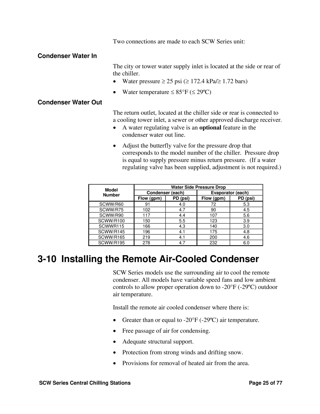
•Adjust the butterfly valve for the pressure drop that corresponds to the model number of the chiller. Pressure drop is equal to supply pressure minus return pressure. (If a water regulating valve has been supplied, adjustment is not required.)
Model |
| Water Side Pressure Drop |
| ||
Condenser (each) | Evaporator (each) | ||||
Number | |||||
Flow (gpm) | PD (psi) | Flow (gpm) | PD (psi) | ||
| |||||
SCWW/R60 | 91 | 4.0 | 72 | 5.3 | |
SCWW/R75 | 102 | 4.7 | 90 | 4.5 | |
SCWW/R90 | 117 | 4.4 | 107 | 5.6 | |
SCWW/R100 | 150 | 5.5 | 123 | 3.9 | |
SCWWR115 | 166 | 4.3 | 140 | 3.0 | |
SCWW/R145 | 196 | 4.1 | 175 | 4.8 | |
SCWW/R165 | 219 | 4.1 | 200 | 4.6 | |
SCWW/R195 | 278 | 4.7 | 232 | 6.0 | |
3-10 Installing the Remote Air-Cooled Condenser
SCW Series models use the surrounding air to cool the remote condenser. All models have variable speed fans and low ambient controls to allow proper operation down to
Install the remote air cooled condenser where there is:
•Greater than or equal to
•Free passage of air for condensing.
•Adequate structural support.
•Protection from strong winds and drifting snow.
•Provisions for removal of heated air from the area.
SCW Series Central Chilling Stations | Page 25 of 77 |
