SUPERSERVER
Figure 5-2. Front Control Panel Header Pins (JF1)
Ground
X
Power LED
HDD LED
NIC1 LED
NIC2 LED
OH/Fan Fail LED
PWR Fail LED
Ground
Ground
20 | 19 |
| NMI |
| X |
| Vcc |
Vcc
Vcc
Vcc
Vcc
Vcc
Reset Reset Button
PWR | Power Button |
|
2 1
5-4 I/O Ports
The I/O ports are color coded in conformance with the PC 99 specification. See Figure
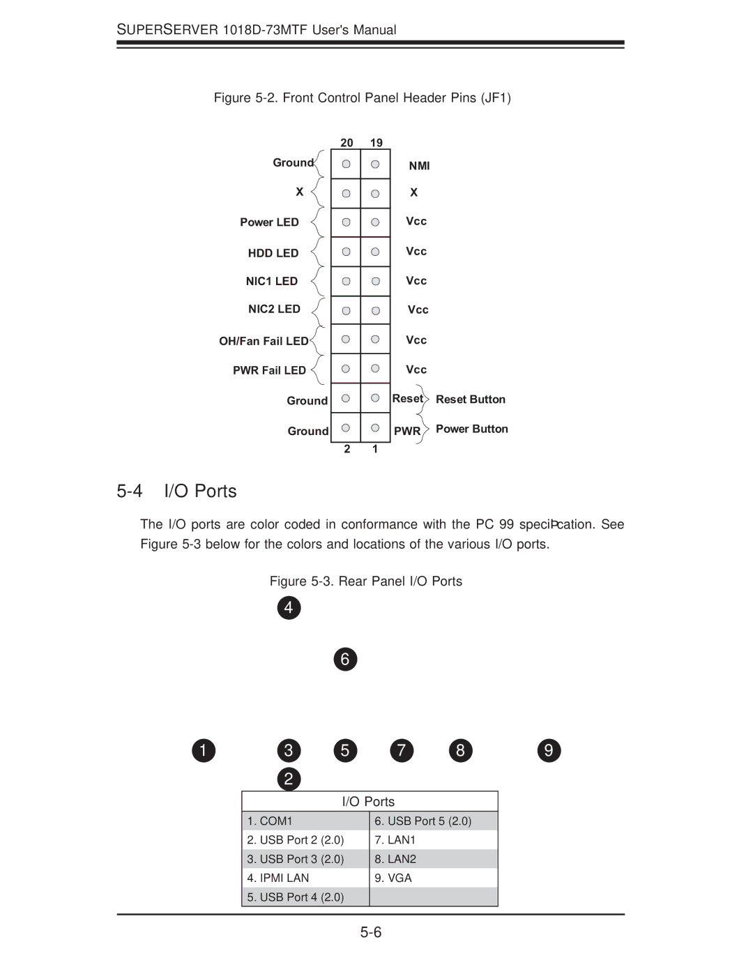
Figure 5-3. Rear Panel I/O Ports
14
16
1 | 13 | 15 | 17 | 18 | 19 |
12
I/O Ports
1.COM1
2.USB Port 2 (2.0)
3.USB Port 3 (2.0)
4.IPMI LAN
5.USB Port 4 (2.0)
6.USB Port 5 (2.0)
7.LAN1
8.LAN2
9.VGA