SUPERSERVER
5-8 Connector Definitions
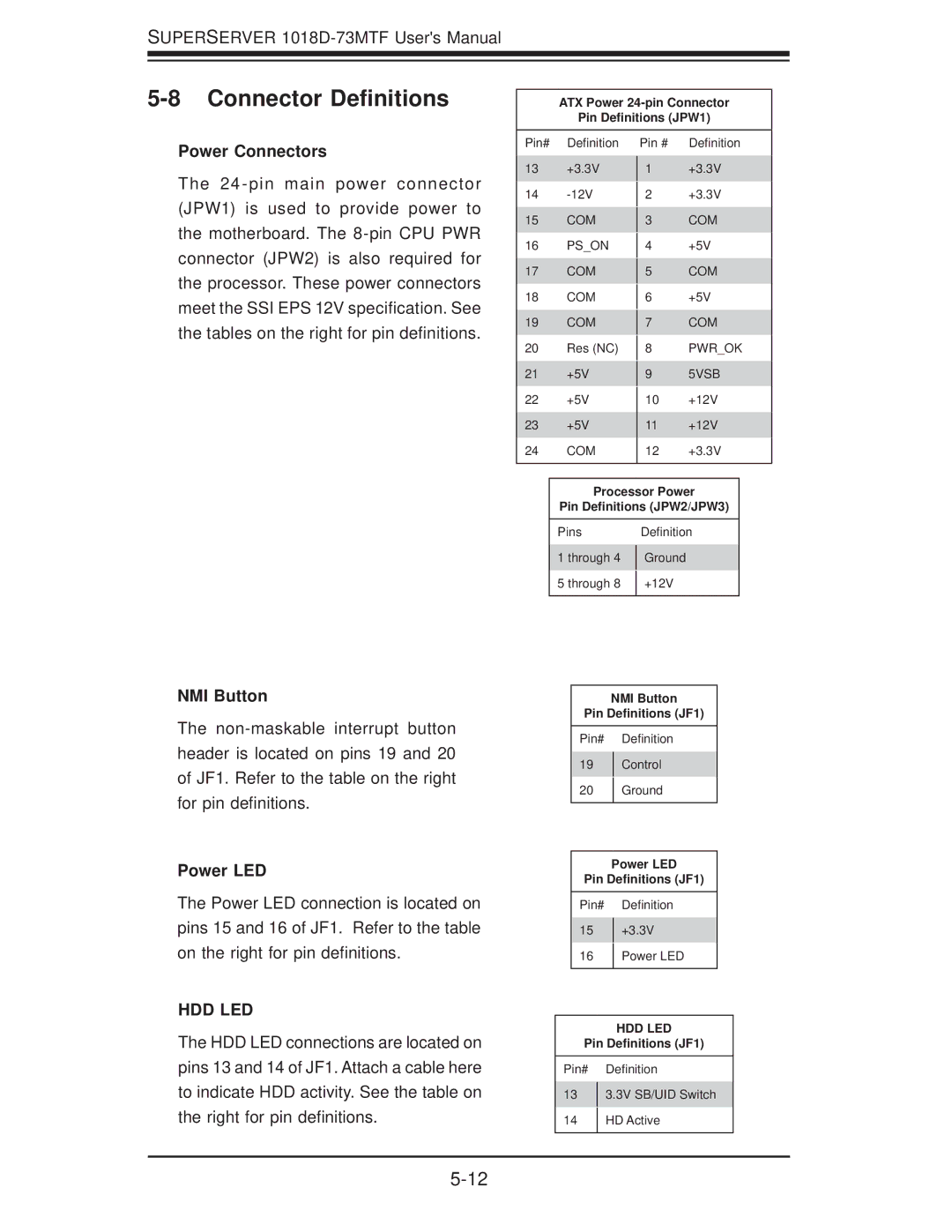
ATX Power
Pin Definitions (JPW1)
Power Connectors
The 24
Pin# Definition
13+3.3V
14
15COM
16PS_ON
17COM
18COM
19COM
20Res (NC)
21+5V
22+5V
23+5V
24COM
Pin # Definition
1+3.3V
2+3.3V
3COM
4+5V
5COM
6+5V
7COM
8PWR_OK
95VSB
10+12V
11+12V
12+3.3V
NMI Button
The
Power LED
The Power LED connection is located on pins 15 and 16 of JF1. Refer to the table on the right for pin definitions.
HDD LED
The HDD LED connections are located on pins 13 and 14 of JF1. Attach a cable here to indicate HDD activity. See the table on the right for pin definitions.
Processor Power
Pin Definitions (JPW2/JPW3)
Pins |
| Definition |
1 through 4 |
| Ground |
| ||
5 through 8 |
| +12V |
| ||
|
|
|
NMI Button
Pin Definitions (JF1)
Pin# Definition
19Control
20Ground
Power LED
Pin Definitions (JF1)
Pin# Definition
15+3.3V
16Power LED
HDD LED
Pin Definitions (JF1)
Pin# Definition
133.3V SB/UID Switch
14HD Active