Chapter 5: Advanced Motherboard Setup
NIC1/NIC2 (LAN1/LAN2)
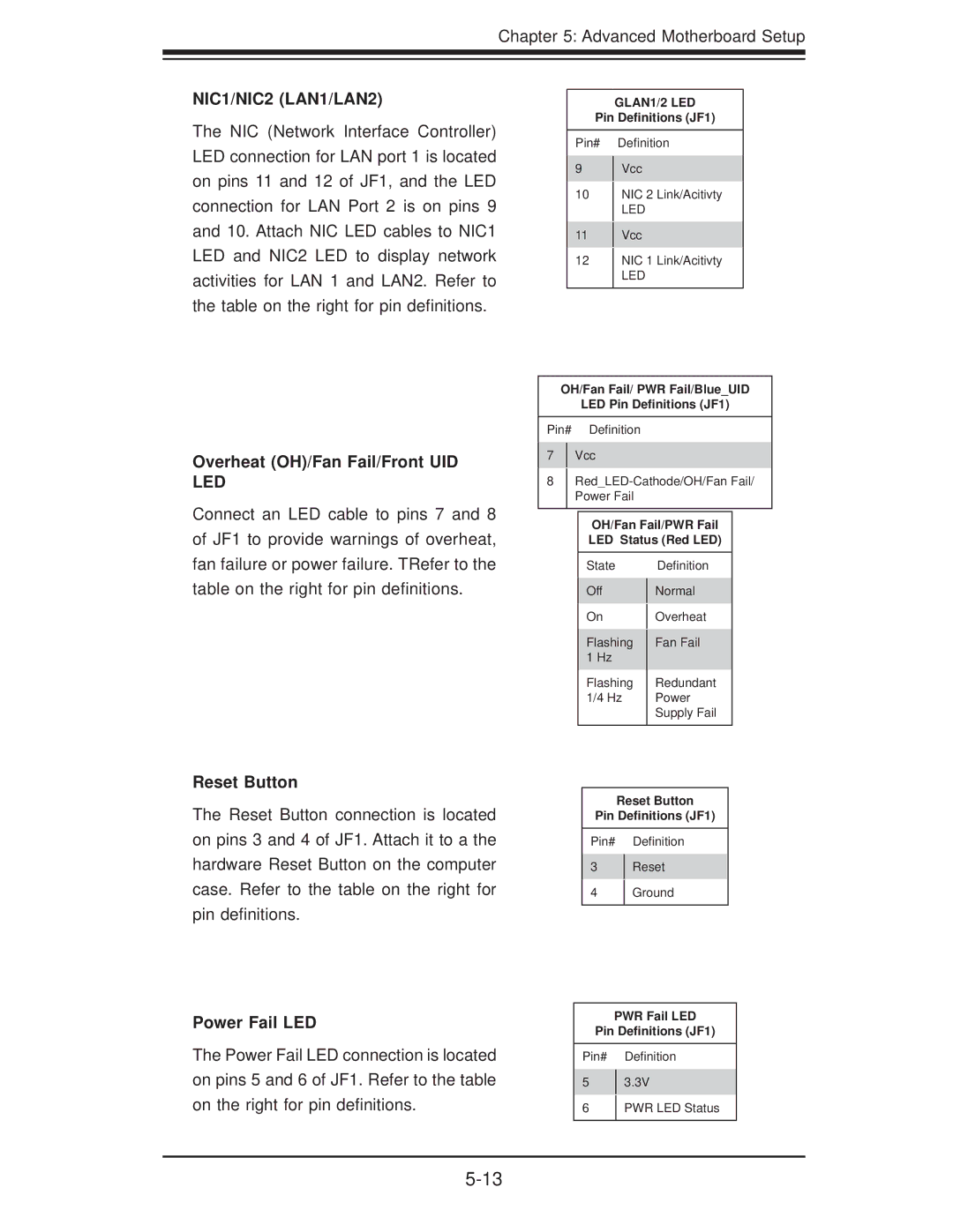
The NIC (Network Interface Controller) LED connection for LAN port 1 is located on pins 11 and 12 of JF1, and the LED connection for LAN Port 2 is on pins 9 and 10. Attach NIC LED cables to NIC1 LED and NIC2 LED to display network activities for LAN 1 and LAN2. Refer to the table on the right for pin definitions.
Overheat (OH)/Fan Fail/Front UID LED
Connect an LED cable to pins 7 and 8 of JF1 to provide warnings of overheat, fan failure or power failure. TRefer to the table on the right for pin definitions.
GLAN1/2 LED
Pin Definitions (JF1)
Pin# Definition
9Vcc
10NIC 2 Link/Acitivty
LED
11Vcc
12NIC 1 Link/Acitivty
LED
OH/Fan Fail/ PWR Fail/Blue_UID
LED Pin Definitions (JF1)
Pin# Definition
7Vcc
8
OH/Fan Fail/PWR Fail
LED Status (Red LED)
State |
| Definition |
Off |
| Normal |
| ||
On |
| Overheat |
| ||
Flashing |
| Fan Fail |
| ||
1 Hz |
|
|
Flashing |
| Redundant |
1/4 Hz |
| Power |
|
| Supply Fail |
|
|
|
Reset Button
The Reset Button connection is located on pins 3 and 4 of JF1. Attach it to a the hardware Reset Button on the computer case. Refer to the table on the right for pin definitions.
Power Fail LED
The Power Fail LED connection is located on pins 5 and 6 of JF1. Refer to the table on the right for pin definitions.
Reset Button
Pin Definitions (JF1)
Pin# Definition
3Reset
4Ground
PWR Fail LED
Pin Definitions (JF1)
Pin# Definition
53.3V
6PWR LED Status