SUPERSERVER
Power Button
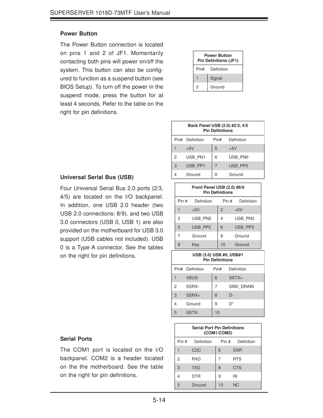
The Power Button connection is located on pins 1 and 2 of JF1. Momentarily contacting both pins will power on/off the system. This button can also be config- ured to function as a suspend button (see BIOS Setup). To turn off the power in the suspend mode, press the button for at least 4 seconds. Refer to the table on the right for pin definitions.
Universal Serial Bus (USB)
Four Universal Serial Bus 2.0 ports (2/3, 4/5) are located on the I/O backpanel.
Power Button
Pin Definitions (JF1)
Pin# Definition
1Signal
2Ground
Back Panel USB (2.0) #2/3, 4/5
Pin Definitions
Pin# | Definition | Pin# | Definition | |||
1 | +5V |
| +5V |
| ||
5 |
| |||||
2 | USB_PN1 |
| USB_PN0 |
| ||
6 |
| |||||
3 | USB_PP1 |
| USB_PP0 |
| ||
7 |
| |||||
4 | Ground |
| Ground |
| ||
8 |
| |||||
|
|
|
|
|
| |
|
|
|
|
| ||
|
| Front Panel USB (2.0) #8/9 | ||||
|
| Pin Definitions | ||||
In addition, one USB 2.0 header (two USB 2.0 connections: 8/9), and two USB
3.0 connectors (USB 0, USB 1) are also |
provided on the motherboard for USB 3.0 |
support (USB cables not included). USB |
0 is a Type A connector. See the tables |
Pin # Definition
1 | +5V |
3 | USB_PN2 |
5 | USB_PP2 |
7Ground
9Key
Pin # Definition
2 | +5V |
4 | USB_PN3 |
6 | USB_PP3 |
8Ground
10Ground
on the right for pin definitions. |
USB (3.0) USB #0, USB#1
Pin Definitions
Pin# Definition
1VBUS
2SSRX-
3SSRX+
4Ground
5SSTX-
Pin# Definition
6SSTX+
7GND_DRAIN
8D-
9D*
10
Serial Port Pin Definitions
(COM1/COM2)
Serial Ports
The COM1 port is located on the I/O backpanel. COM2 is a header located on the the motherboard. See the table on the right for pin definitions.
Pin # Definition
1CDC
2RXD
3TXD
4DTR
5Ground
Pin # Definition
6DSR
7RTS
8CTS
9RI
10NC