SUPERSERVER
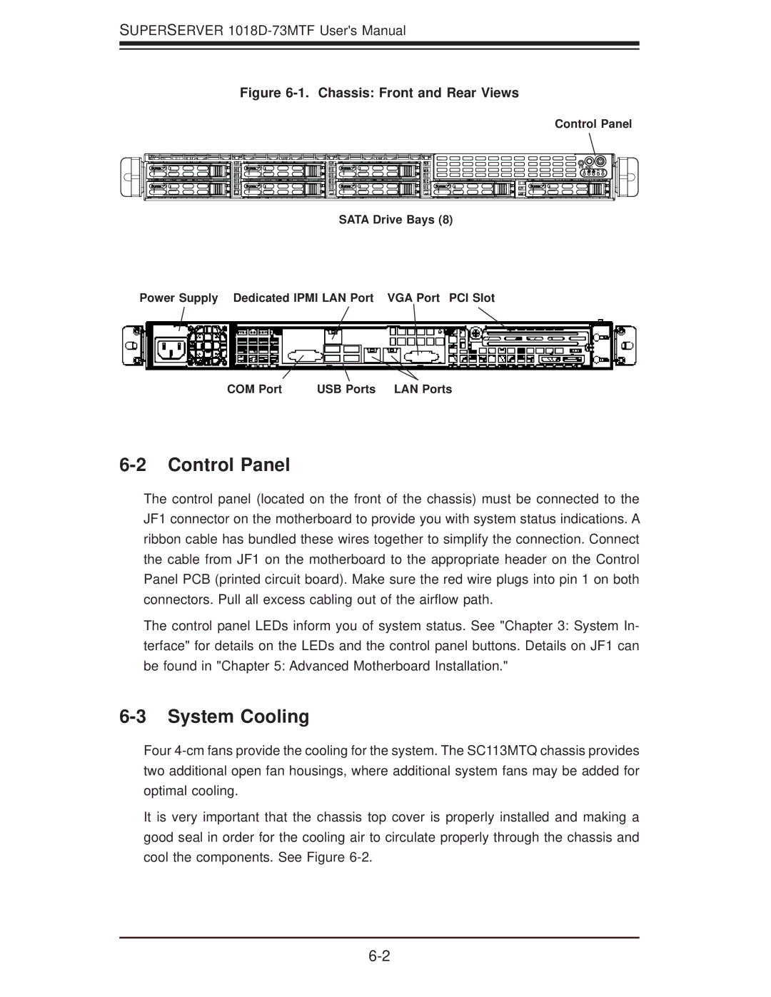
Figure 6-1. Chassis: Front and Rear Views
Control Panel
SATA Drive Bays (8)
Power Supply Dedicated IPMI LAN Port VGA Port PCI Slot
COM Port | USB Ports LAN Ports |
6-2 Control Panel
The control panel (located on the front of the chassis) must be connected to the JF1 connector on the motherboard to provide you with system status indications. A ribbon cable has bundled these wires together to simplify the connection. Connect the cable from JF1 on the motherboard to the appropriate header on the Control Panel PCB (printed circuit board). Make sure the red wire plugs into pin 1 on both connectors. Pull all excess cabling out of the airflow path.
The control panel LEDs inform you of system status. See "Chapter 3: System In- terface" for details on the LEDs and the control panel buttons. Details on JF1 can be found in "Chapter 5: Advanced Motherboard Installation."
6-3 System Cooling
Four
It is very important that the chassis top cover is properly installed and making a good seal in order for the cooling air to circulate properly through the chassis and cool the components. See Figure