Manuals
/
SUPER MICRO Computer
/
Computer Equipment
/
Server
SUPER MICRO Computer
2042G-TRF, 2042G-6RF, AS2042G72RF4
user manual
Super
Models:
AS2042G72RF4
2042G-TRF
2042G-6RF
1
1
94
94
Download
94 pages
30.6 Kb
1
2
3
4
5
6
7
8
Install
Amibios Error Beep Codes
Onboard Indicators
Connecting Cables
Reset
Accessing the Drive Bays
Advanced Serverboard Setup
Connector Description
IDE Detect Timeout Sec
Enabling Sata RAID in the Bios
Page 1
Image 1
S
UPER
®
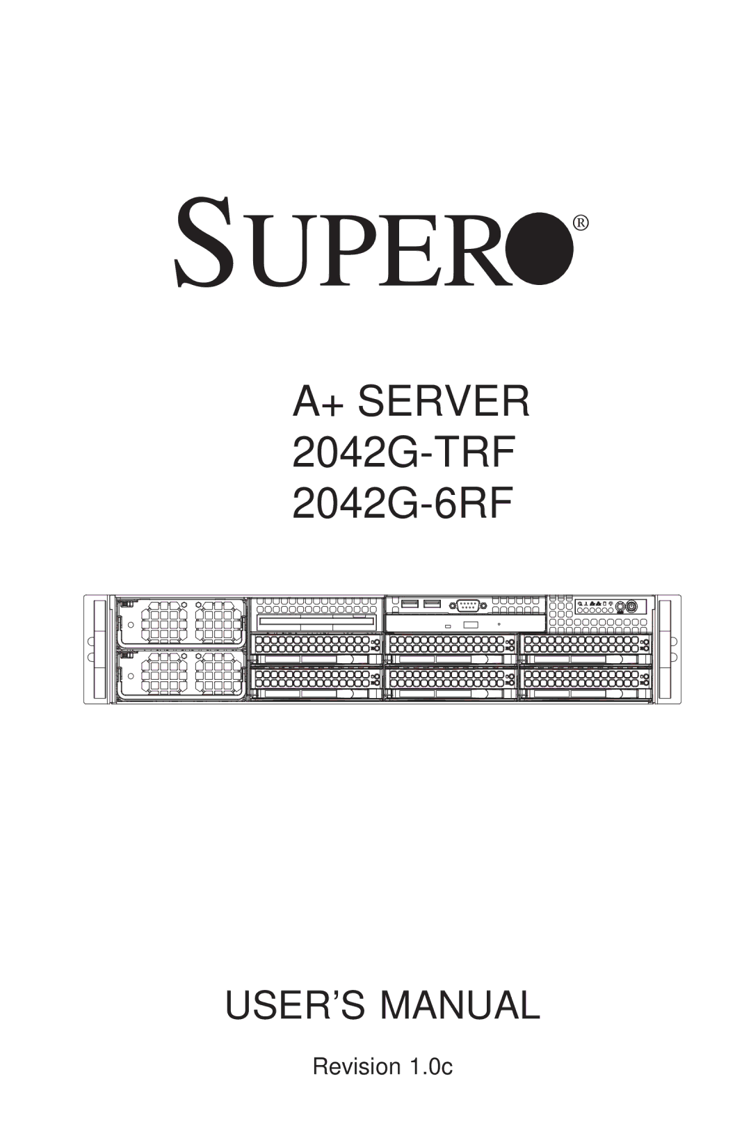
A+ SERVER
2042G-TRF
2042G-6RF
USER’S MANUAL
Revision 1.0c
Page 1
Page 2
Page 1
Image 1
Page 1
Page 2
Contents
Super
Page
About This Manual
Preface
Manual Organization
Advanced Chassis Setup
Advanced Serverboard Setup
Bios
Preface
Table of Contents
System Interface
Advanced Chassis Setup
Appendix C System Specifications
Page
Overview
Chapter Introduction
Processors Memory
Serverboard Features
SAS AS-2042G-6RF Only
Serial ATA
Ethernet Ports
Other Features
Onboard Controllers/Ports
Graphics Controller
Server Chassis Features
AMD SR5690/SP5100 Chipset System Block Diagram
Headquarters
Contacting Supermicro
Europe
Asia-Pacific
Preparing for Setup
Chapter Server Installation
Unpacking the System
Choosing a Setup Location
Rack Mounting Considerations
Ambient Operating Temperature
Installing the Inner Rails
Installing the System into a Rack
Installing the Outer Rails
Identifying the Sections of the Rack Rails
Installing the Server into a Rack
Installing the Server into the Rack
Accessing the Inside of the System
Checking the Serverboard Setup
Checking the Components and Setup
Providing Power
Preparing to Power On
Checking the Drives
Checking the Airflow
Page
Power
Reset
Chapter System Interface
Control Panel Buttons
Control Panel LEDs
Power Fail
Overheat/Fan Fail
HDD
SAS Drive Carrier LEDs
Page
Electrical Safety Precautions
Chapter System Safety
General Safety Precautions
ESD Precautions
Installing the Onboard CR2032 Battery
Operating Precautions
Precautions
Chapter Advanced Serverboard Setup
Handling the Serverboard
Installing to the Chassis
Serverboard Installation
Unpacking
Connecting Data Cables
Connecting Cables
Connecting Power Cables
Connecting the Control Panel
Rear I/O Ports
I/O Ports
Installation Procedure
Installing the Processor and Heatsink
Installing the Processors
Socket, which may damage
SNK-0043P Heatsink
Installing a Passive CPU Heatsink
Installing Memory
Installing Memory
Support
Maximum Memory
Channel
# Dimms CPU
Possible System Memory Allocation & Availability
Per Channel Dimm Populations Options
Dimm Type
Max. MHz Max. GB 5V DIMMs 35V DIMMs
Adding PCI Add-On Cards
Installing an Add-on Card
Serverboard Details
Jumper Description Default Setting
H8QG6/i-F Quick Reference
Connector Description
Advanced Serverboard Setup
Power Connectors
Connector Definitions
Reset Connector
HDD/FP UID Switch
Power Fail LED
Power LED Connector
Overheat OH/Fan Fail/PWR Fail/UID
Universal Serial Bus Ports
Video Connector
USB Headers
Fan Headers
SMBus Header
Power I2C
Wake-On-LAN
Chassis Intrusion
Power LED/Speaker
Overheat LED
ATX PS/2 Keyboard and PS/2 Mouse Ports
Unit Identifier Button
Compact Flash Card PWR Connector
Trusted Platform Module Header
LAN1/2 Ethernet Ports
Explanation of Jumpers
Jumper Settings
Cmos Clear
JBT1 contact pads
VGA Enable/Disable
Watch Dog Enable/Disable
LAN1/2 Enable/Disable
SAS Enable/Disable
BMC Jumper Enable JPB1 Jumper Settings
Backpanel USB Wake-Up Enable JPUSB1 Jumper Settings
USB Wake-Up
BMC Jumper
Power LED
Onboard Indicators
LAN1/LAN2 LEDs
Dedicated Ipmi LAN LEDs
Sata Ports
SAS and Sata Drive Connections
SAS Ports H8QG6-F Only
Sata Ports Pin Definitions
Enabling Sata RAID
Installing the OS/SATA Driver
Serial ATA Sata
Building a Driver Diskette
Bios Setup Screen
Enabling Sata RAID in the Bios
Installing the RAID Driver During OS Installation
Using the Adaptec RAID Utility
Driver/Tool Installation Display Screen
Installing Drivers
Supero Doctor
Page
Page
System Fans
Control Panel
Port
Replacing System Fans
System Fan Failure
Removing a fan
Accessing the Drive Bays
Drive Bay Installation/Removal
SAS/SATA Drive Installation
Installing a new fan
Installing/removing SAS/SATA drives
Page
SAS/SATA Drive Backplane
DVD-ROM Drive Installation
SAS/SATA Backplane Connections
Power Supply Failure
Power Supply
Removing/Replacing the Power Supply
Removing the power supply
Removing a Power Supply Module
Page
Chapter
Starting the Setup Utility
Introduction
Boot Features
Advanced Settings Menu
Main Menu
Processor & Clock Options
NorthBridge Chipset Configuration Memory Configuration
Advanced Chipset Control
DRAM Timing Configuration
ECC Configuration
Primary/Secondary/Third IDE Master/Slave
IDE/SATA Configuration
IDE Detect Timeout Sec
DMA Mode
A.R.T
Bit Data Transfer
SuperI/O Configuration
PCI/PNP Configuration
Remote Access Configuration
System Fan Monitor
Hardware Health Configuration
ACPI Configuration
View BMC System Event Log
IPMI Configuration
Set LAN Configuration
IP Address
Event Log Configuration
Security Settings Menu
MAC Address
Subnet Mask
Boot Settings Menu
Network Drives
Exit Menu
Amibios Error Beep Codes
Appendix a Bios Error Beep Codes
Beep Code Error Message Description
Page
Installing Windows to a RAID System
Appendix B Installing Windows
Installing Windows to a Non-RAID System
Appendix C System Specifications
Power Supply
Weight
Expansion Slots
Serverboard
Regulatory Compliance
From front
Top
Page
Image
Contents