A+ SERVER
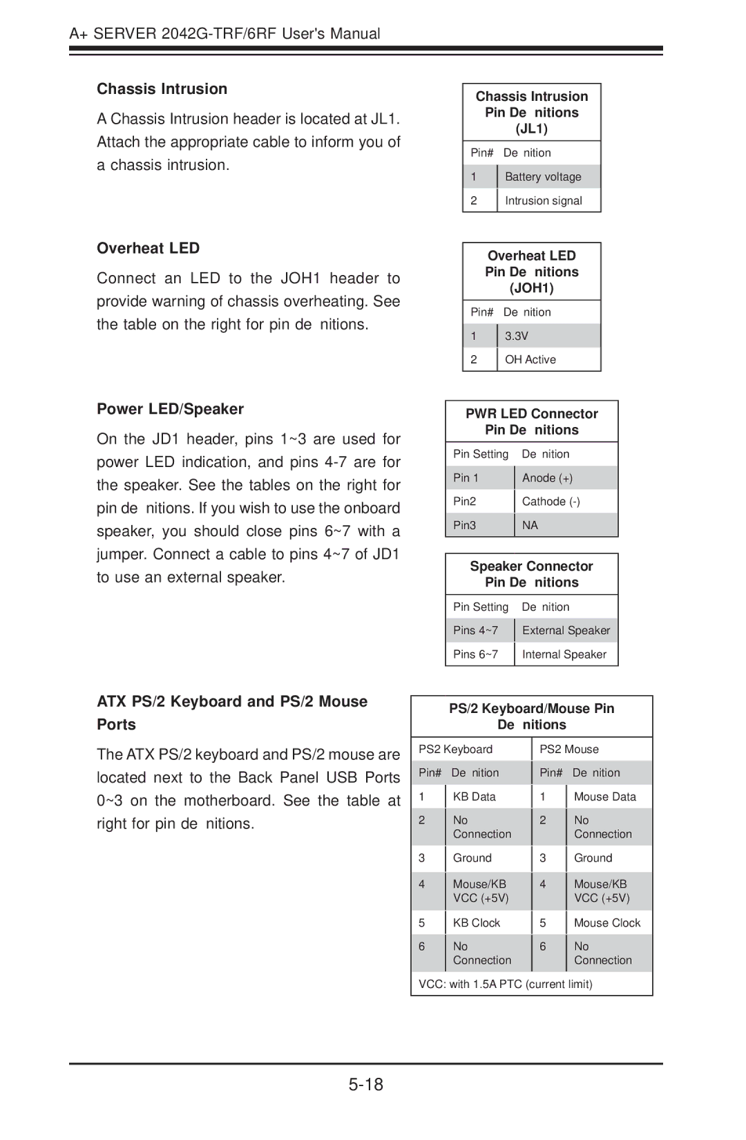
Chassis Intrusion
A Chassis Intrusion header is located at JL1. Attach the appropriate cable to inform you of a chassis intrusion.
Overheat LED
Connect an LED to the JOH1 header to provide warning of chassis overheating. See the table on the right for pin definitions.
Power LED/Speaker
On the JD1 header, pins 1~3 are used for power LED indication, and pins
Chassis Intrusion
Pin Definitions
(JL1)
Pin# Definition
1Battery voltage
2Intrusion signal
Overheat LED
Pin Definitions
(JOH1)
Pin# Definition
13.3V
2OH Active
PWR LED Connector
Pin Definitions
Pin Setting Definition
Pin 1 | Anode (+) | |
Pin2 | Cathode | |
Pin3 | NA | |
|
|
Speaker Connector
Pin Definitions
Pin Setting Definition
Pins 4~7 External Speaker
Pins 6~7 Internal Speaker
ATX PS/2 Keyboard and PS/2 Mouse Ports
The ATX PS/2 keyboard and PS/2 mouse are located next to the Back Panel USB Ports 0~3 on the motherboard. See the table at right for pin definitions.
PS/2 Keyboard/Mouse Pin
Definitions
PS2 Keyboard | PS2 Mouse | ||||
Pin# |
| Definition | Pin# |
| Definition |
|
| ||||
1 |
| KB Data | 1 |
| Mouse Data |
|
| ||||
2 |
| No | 2 |
| No |
|
| ||||
|
| Connection |
|
| Connection |
3 |
| Ground | 3 |
| Ground |
|
| ||||
4 |
| Mouse/KB | 4 |
| Mouse/KB |
|
| ||||
|
| VCC (+5V) |
|
| VCC (+5V) |
5 |
| KB Clock | 5 |
| Mouse Clock |
|
| ||||
6 |
| No | 6 |
| No |
|
| ||||
|
| Connection |
|
| Connection |
|
|
|
|
|
|
VCC: with 1.5A PTC (current limit)