SUPERSERVER
PWR_ON
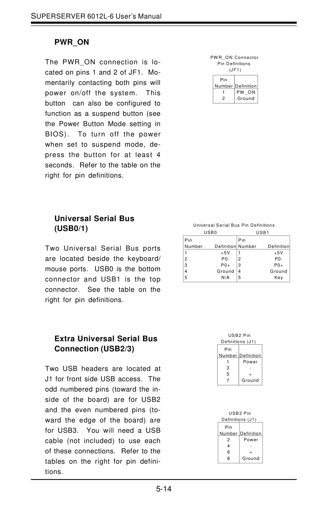
The PWR_ON connection is lo- cated on pins 1 and 2 of JF1. Mo- mentarily contacting both pins will power on/off the system. This button can also be configured to function as a suspend button (see the Power Button Mode setting in BIOS). To turn off the power when set to suspend mode, de- press the button for at least 4 seconds. Refer to the table on the right for pin definitions.
P W R _ O N C o nne c to r
P in D e finitio ns
(J F 1 )
P in
N umbe r D efinition
1P W _O N
2G roun d
Universal Serial Bus (USB0/1)
Two Universal Serial Bus ports are located beside the keyboard/ mouse ports. USB0 is the bottom connector and USB1 is the top connector. See the table on the right for pin definitions.
Extra Universal Serial Bus Connection (USB2/3)
Two USB headers are located at J1 for front side USB access. The odd numbered pins (toward the in- side of the board) are for USB2 and the even numbered pins (to- ward the edge of the board) are for USB3. You will need a USB cable (not included) to use each of these connections. Refer to the tables on the right for pin defini- tions.
U nive rs a l S e ria l B us P in D e finitio n s
| U S B 0 |
| U S B 1 | |
Pin |
| Pin |
|
|
Number | Definition | Number | Definition | |
1 | +5V | 1 |
| +5V |
2 | P0- | 2 |
| P0- |
3 | P0+ | 3 |
| P0+ |
4 | G round | 4 |
| G round |
5 | N/A | 5 |
| Key |
|
|
|
|
|
U S B 2 P in
D e finitio ns (J 1 )
P in
N umb er D efinition
1 | P ower |
3 | - |
5 | + |
7 | G roun d |
U S B 3 P in
D e finitio ns (J 1 )
P in |
|
N umber | D efinition |
2 | P ower |
4 | - |
6 | + |
8 | G round |
|
|