Chapter 5: Advanced Motherboard Setup
NIC2 LED
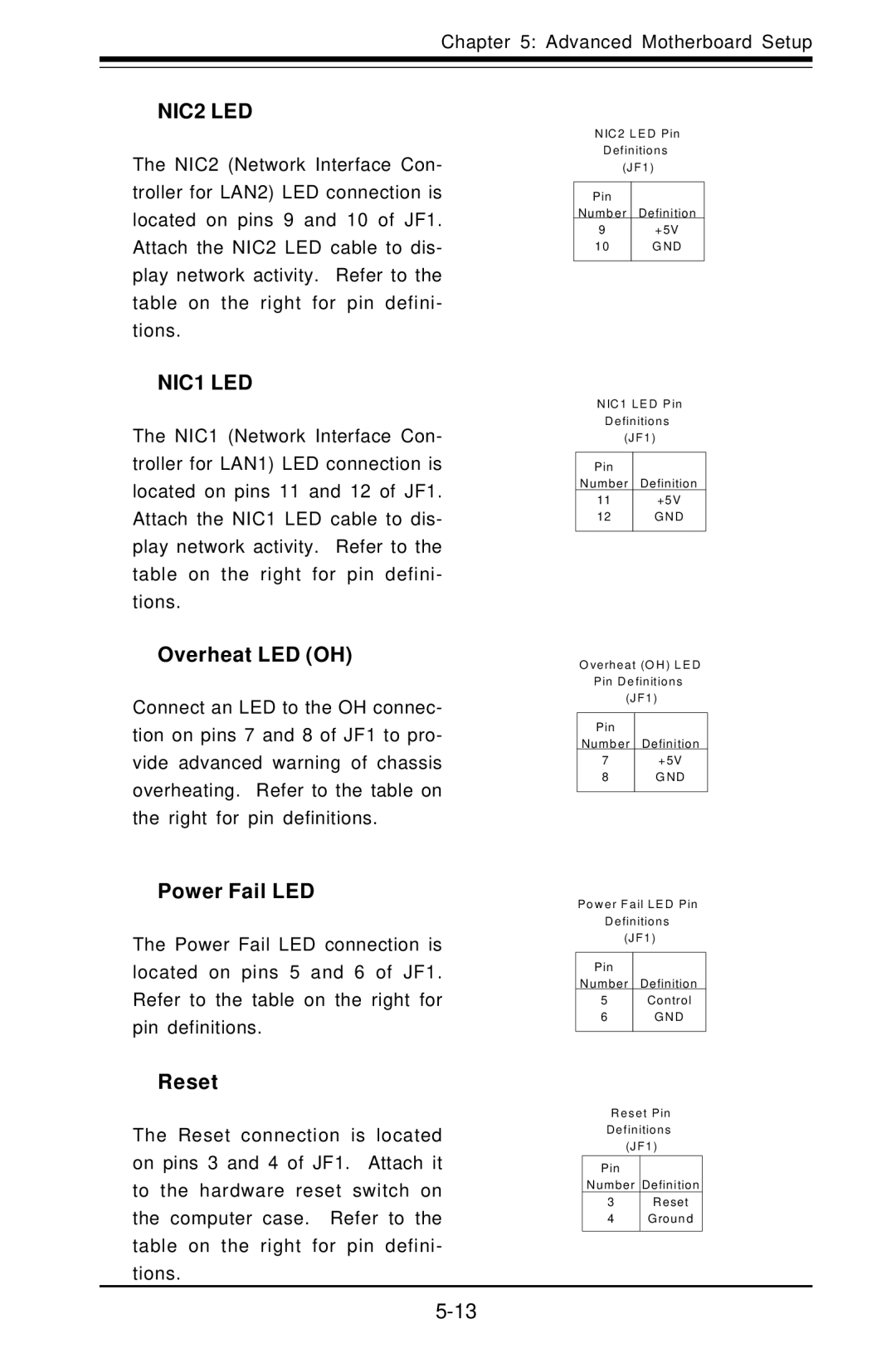
The NIC2 (Network Interface Con- troller for LAN2) LED connection is located on pins 9 and 10 of JF1. Attach the NIC2 LED cable to dis- play network activity. Refer to the table on the right for pin defini- tions.
NIC1 LED
The NIC1 (Network Interface Con- troller for LAN1) LED connection is located on pins 11 and 12 of JF1. Attach the NIC1 LED cable to dis- play network activity. Refer to the table on the right for pin defini- tions.
Overheat LED (OH)
Connect an LED to the OH connec- tion on pins 7 and 8 of JF1 to pro- vide advanced warning of chassis overheating. Refer to the table on the right for pin definitions.
Power Fail LED
The Power Fail LED connection is located on pins 5 and 6 of JF1. Refer to the table on the right for pin definitions.
Reset
The Reset connection is located on pins 3 and 4 of JF1. Attach it to the hardware reset switch on the computer case. Refer to the table on the right for pin defini- tions.
N IC 2 L E D P in
D e finitio ns
(J F 1 )
P in |
|
N umb er | D efinition |
9 | +5V |
10 | G N D |
|
|
N IC 1 L E D P in D e finitio ns (J F 1 )
P in |
|
N umber | D efinition |
11 | +5V |
12 | G N D |
|
|
O ve rh e a t (O H ) L E D
P in D e finitio ns
(J F 1 )
P in
N umb er D efinition
7+5V
8G N D
P o w e r F a il L E D P in
D e finitio ns
(J F 1 )
P in
N umber D efinition
5C ontrol
6G N D
R e s e t P in D e finitio ns (J F 1 )
P in
N umb er D efinition
3R eset
4G roun d