SUPERSERVER
5-8 Connector Definitions
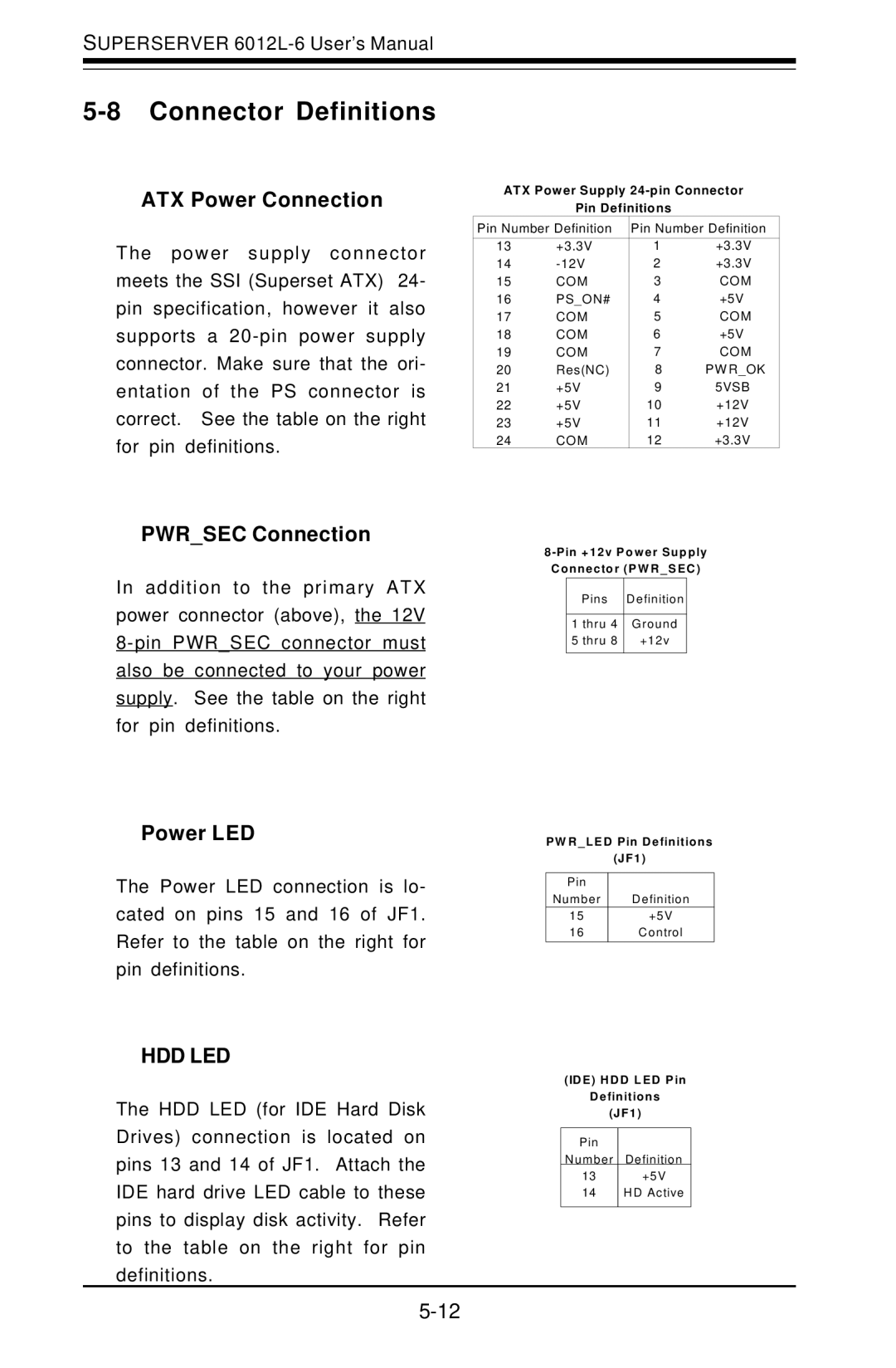
ATX Power Connection
The power supply connector meets the SSI (Superset ATX) 24- pin specification, however it also supports a
ATX Power Supply
Pin Definitions
Pin Number Definition | Pin Number Definition | ||
|
|
|
|
13 | +3.3V | 1 | +3.3V |
14 | 2 | +3.3V | |
15 | COM | 3 | COM |
16 | PS_ON# | 4 | +5V |
17 | COM | 5 | COM |
18 | COM | 6 | +5V |
19 | COM | 7 | COM |
20 | Res(NC) | 8 | PW R_OK |
21 | +5V | 9 | 5VSB |
22 | +5V | 10 | +12V |
23 | +5V | 11 | +12V |
24 | COM | 12 | +3.3V |
PWR_SEC Connection
In addition to the primary ATX power connector (above), the 12V
Power LED
The Power LED connection is lo- cated on pins 15 and 16 of JF1. Refer to the table on the right for pin definitions.
HDD LED
The HDD LED (for IDE Hard Disk Drives) connection is located on pins 13 and 14 of JF1. Attach the IDE hard drive LED cable to these pins to display disk activity. Refer to the table on the right for pin definitions.
8
| Pins | Definition |
|
|
|
1 | thru 4 | G round |
5 | thru 8 | +12v |
|
|
|
P W R _ L E D P in D e finitio ns
(J F 1 )
P in |
|
N umber | D efinition |
15 | +5V |
16 | C ontrol |
(ID E ) H D D L E D P in
D e finitio ns
(J F 1 )
P in
N umber D efinition
13 | +5V |
14 | HD Active |