SUPERSERVER
5-9 Onboard Indicators
LAN1/LAN2 LEDs
Each of the Ethernet ports (located be- side the VGA port) has a yellow and a green LED. See the table on the right for the functions associated with these LEDs.
CR5 LED
CR5 is an onboard LED that serves as a power indicator. See the table on the right for the meaning of each of the three colors dis- played by CR5.
1 0 0 M b L A N LE D
Ind ic a to rs (L AN 1 /L A N 2 )
LED |
|
Color | Definition |
G reen | Connected |
Yellow | Active |
|
|
O nb o a rd L E D P o w e r
Ind ic a to r (C R 5)
LE D |
|
C olor | D efinition |
G reen | Power O n |
Y ellow | Standby Mode |
R ed | W rong CPU |
|
|
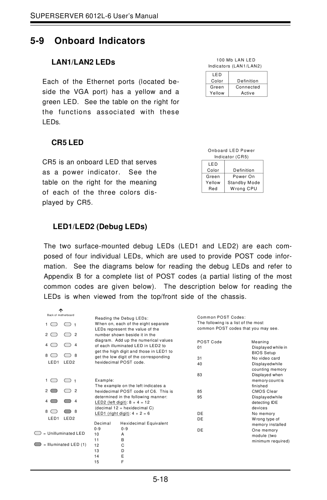
LED1/LED2 (Debug LEDs)
The two
Back of motherboard
1 ![]()
![]() 1
1
2 ![]()
![]() 2
2
4 ![]()
![]() 4
4
8 ![]()
![]() 8
8
LED1 LED2
1 ![]()
![]() 1
1
2 ![]()
![]() 2
2
4 ![]()
![]() 4
4
8 ![]()
![]() 8
8
LED1 LED2
Re ading the D ebug LEDs:
W hen on, each of the eight separate LEDs represent the value of the number shown beside it in the diagram. Add up the numerical values of each illuminated LED in LED2 to get the high digit and those in LED1 to get the low digit of the corresponding hexidecimal PO ST code.
Exam ple:
The example on the left indicates a hexidecimal PO ST code of C6. This is determined in the following manner: LED2 (left digit): 8 + 4 = 12 (decimal 12 = hexidecimal C)
LED1 (right digit): 4 + 2 = 6
De cim a l He xidecim a l Equivalent
Com m on PO ST Codes :
The following is a list of the most common POST codes that you may see.
PO ST C ode | M eaning |
01 | Displayed while in |
| BIO S Setup |
31 | No video card |
40 | Displayedwhile |
| counting memory |
83Displayed when memory count is
| finished |
85 | CMO S Clear |
95Displayedwhile detecting IDE devices
DE | No memory |
DE | W rong type of |
| memory installed |
| ||
= Unilluminated LED | 10 | A |
| 11 | B |
= Illuminated LED (1) | 12 | C |
| 13 | D |
| 14 | E |
| 15 | F |
DE | One memory |
| module (two |
| minimum required) |