![]()
![]()
2-7 Connecting Cables
This section provides brief descriptions and
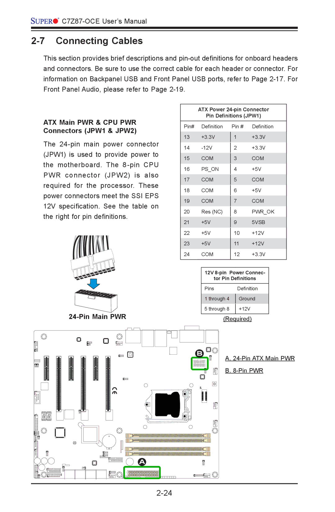
ATX Main PWR & CPU PWR Connectors (JPW1 & JPW2)
The
24-Pin Main PWR
ATX Power
Pin Definitions (JPW1)
Pin# | Definition | Pin # | Definition | ||
13 | +3.3V |
|
| +3.3V | |
1 | |||||
14 |
|
| +3.3V | ||
2 | |||||
15 | COM |
|
| COM | |
3 | |||||
16 | PS_ON |
|
| +5V | |
4 | |||||
17 | COM |
|
| COM | |
5 | |||||
18 | COM |
|
| +5V | |
6 | |||||
19 | COM |
|
| COM | |
7 | |||||
20 | Res (NC) |
|
| PWR_OK | |
8 | |||||
21 | +5V |
|
| 5VSB | |
9 | |||||
22 | +5V |
|
| +12V | |
10 | |||||
23 | +5V | 11 | +12V | ||
24 | COM | 12 | +3.3V | ||
|
|
|
|
| |
|
|
| |||
| 12V |
| |||
| tor Pin Definitions |
| |||
| Pins |
| Definition |
| |
| 1 through 4 |
| Ground |
| |
|
|
| |||
| 5 through 8 |
| +12V |
|
|
|
|
|
| ||
|
|
|
|
|
|
(Required)
B
A.
B.
A