Chapter 1: Introduction
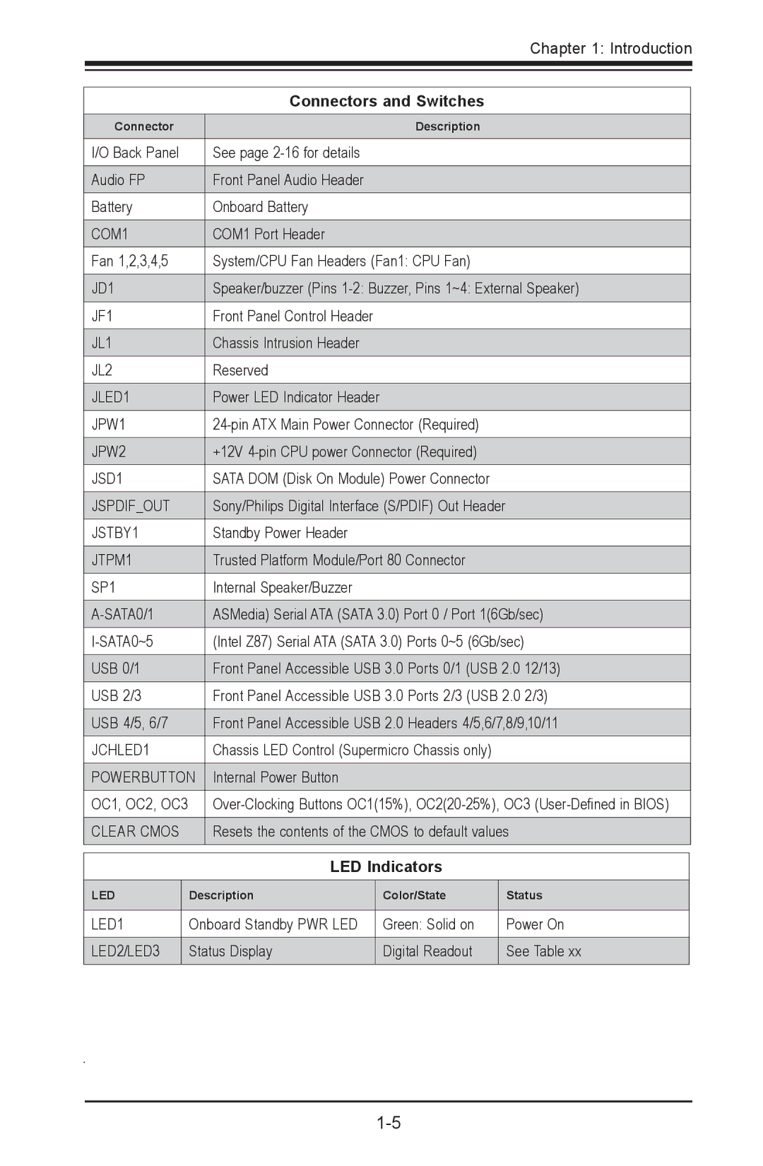
| Connectors and Switches |
Connector | Description |
|
|
I/O Back Panel | See page |
|
|
Audio FP | Front Panel Audio Header |
|
|
Battery | Onboard Battery |
|
|
COM1 | COM1 Port Header |
|
|
Fan 1,2,3,4,5 | System/CPU Fan Headers (Fan1: CPU Fan) |
|
|
JD1 | Speaker/buzzer (Pins |
|
|
JF1 | Front Panel Control Header |
|
|
JL1 | Chassis Intrusion Header |
|
|
JL2 | Reserved |
|
|
JLED1 | Power LED Indicator Header |
|
|
JPW1 | |
|
|
JPW2 | +12V |
|
|
JSD1 | SATA DOM (Disk On Module) Power Connector |
|
|
JSPDIF_OUT | Sony/Philips Digital Interface (S/PDIF) Out Header |
|
|
JSTBY1 | Standby Power Header |
|
|
JTPM1 | Trusted Platform Module/Port 80 Connector |
|
|
SP1 | Internal Speaker/Buzzer |
|
|
ASMedia) Serial ATA (SATA 3.0) Port 0 / Port 1(6Gb/sec) | |
|
|
(Intel Z87) Serial ATA (SATA 3.0) Ports 0~5 (6Gb/sec) | |
|
|
USB 0/1 | Front Panel Accessible USB 3.0 Ports 0/1 (USB 2.0 12/13) |
|
|
USB 2/3 | Front Panel Accessible USB 3.0 Ports 2/3 (USB 2.0 2/3) |
|
|
USB 4/5, 6/7 | Front Panel Accessible USB 2.0 Headers 4/5,6/7,8/9,10/11 |
|
|
JCHLED1 | Chassis LED Control (Supermicro Chassis only) |
|
|
POWERBUTTON | Internal Power Button |
|
|
OC1, OC2, OC3 | |
|
|
CLEAR CMOS | Resets the contents of the CMOS to default values |
|
|
LED Indicators
LED | Description | Color/State | Status |
|
|
|
|
LED1 | Onboard Standby PWR LED | Green: Solid on | Power On |
|
|
|
|
LED2/LED3 | Status Display | Digital Readout | See Table xx |
|
|
|
|