![]()
![]()
![]()
![]()
![]()
![]()
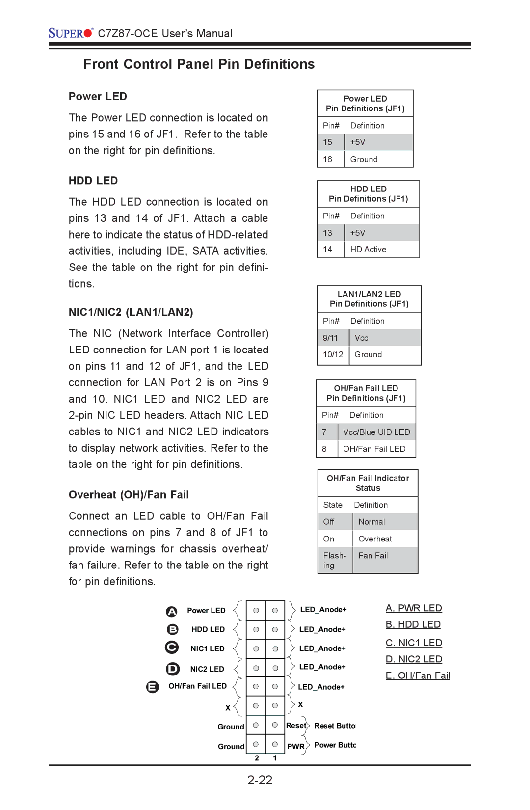
Front Control Panel Pin Definitions
Power LED
The Power LED connection is located on pins 15 and 16 of JF1. Refer to the table on the right for pin definitions.
HDD LED
The HDD LED connection is located on pins 13 and 14 of JF1. Attach a cable here to indicate the status of
NIC1/NIC2 (LAN1/LAN2)
The NIC (Network Interface Controller) LED connection for LAN port 1 is located on pins 11 and 12 of JF1, and the LED connection for LAN Port 2 is on Pins 9 and 10. NIC1 LED and NIC2 LED are
Overheat (OH)/Fan Fail
Connect an LED cable to OH/Fan Fail connections on pins 7 and 8 of JF1 to provide warnings for chassis overheat/ fan failure. Refer to the table on the right for pin definitions.
Power LED
Pin Definitions (JF1)
Pin# Definition
15+5V
16Ground
HDD LED
Pin Definitions (JF1)
Pin# Definition
13+5V
14HD Active
LAN1/LAN2 LED
Pin Definitions (JF1)
Pin# Definition
9/11 | Vcc |
|
|
10/12 Ground
OH/Fan Fail LED
Pin Definitions (JF1)
Pin# Definition
7Vcc/Blue UID LED
8OH/Fan Fail LED
OH/Fan Fail Indicator
Status
State Definition
Off | Normal | |
On | Overheat | |
Flash- | Fan Fail | |
ing |
| |
|
|
APower LED
BHDD LED
CNIC1 LED
DNIC2 LED
EOH/Fan Fail LED
X
Ground
Ground
2 1
LED_Anode+
LED_Anode+
LED_Anode+
LED_Anode+
LED_Anode+
X
Reset Reset Button
PWR Power Butto
A. PWR LED B. HDD LED
C. NIC1 LED D. NIC2 LED E. OH/Fan Fail