Chapter 2: Installation
2-4 Installing DDR3 Memory
Note: Check the Supermicro website for recommended memory mod- ules.
CAUTION
Exercise extreme care when installing or removing DIMM
modules to prevent any possible damage.
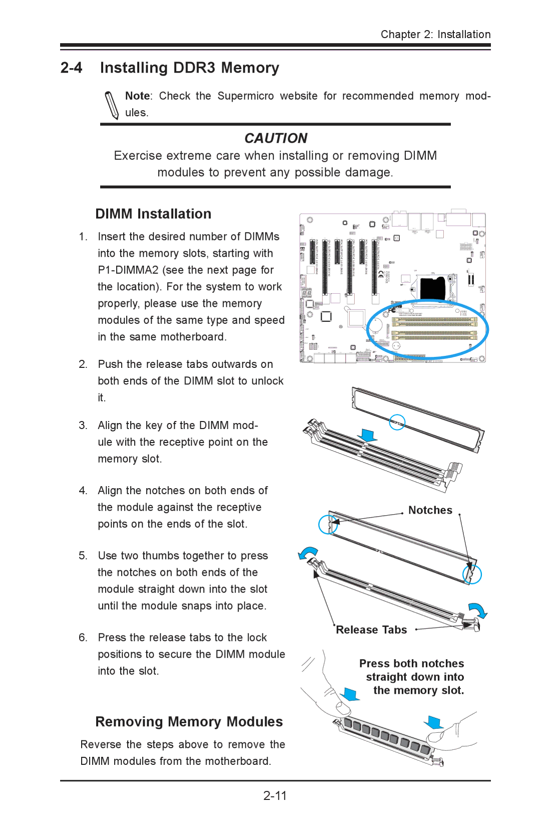
DIMM Installation
1. | Insert the desired number of DIMMs |
| into the memory slots, starting with |
| |
| the location). For the system to work |
| properly, please use the memory |
| modules of the same type and speed |
| in the same motherboard. |
2. | Push the release tabs outwards on |
| both ends of the DIMM slot to unlock |
| it. |
3. | Align the key of the DIMM mod- |
| ule with the receptive point on the |
| memory slot. |
4. | Align the notches on both ends of |
|
| ) |
|
|
) |
|
|
|
|
PCH SLOT1 | CPU SLOT2 | PCH SLOT3 | CPU SLOT4 | PCH SLOT5 |
2.0 | 3.0 | 2.0 | 3.0 | 2.0 |
X1 (INX4 | X4 (IN X16) | X1 (INX4 | X8 (IN X16) | X1 (INX4) |
6LO |
|
CPU S |
|
T6 |
|
DESIGNEDINUSA | CPU |
CPU | |
| ALWAYS POPULATE BLUE SOCKET FIRST |
| UNB |
+ |
|
| ++ |
X
| the module against the receptive |
| points on the ends of the slot. |
5. | Use two thumbs together to press |
| the notches on both ends of the |
| module straight down into the slot |
| until the module snaps into place. |
6. | Press the release tabs to the lock |
| positions to secure the DIMM module |
| into the slot. |
![]() Notches
Notches
![]() Release Tabs
Release Tabs
Press both notches straight down into ![]() the memory slot.
the memory slot.
Removing Memory Modules
Reverse the steps above to remove the DIMM modules from the motherboard.