Chapter 2: Installation
Universal Serial Bus (USB)
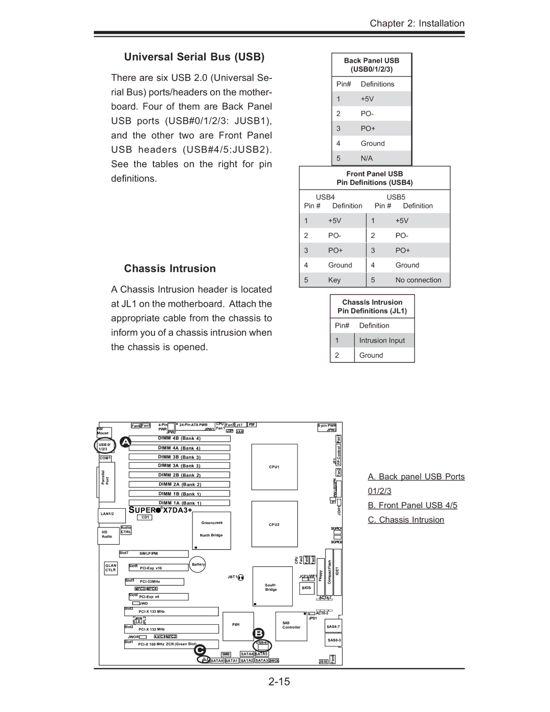
There are six USB 2.0 (Universal Se- rial Bus) ports/headers on the mother- board. Four of them are Back Panel USB ports (USB#0/1/2/3: JUSB1), and the other two are Front Panel USB headers (USB#4/5:JUSB2). See the tables on the right for pin defi nitions.
Chassis Intrusion
A Chassis Intrusion header is located at JL1 on the motherboard. Attach the appropriate cable from the chassis to inform you of a chassis intrusion when the chassis is opened.
Back Panel USB
(USB0/1/2/3)
Pin# Defi nitions
1+5V
2PO-
3PO+
4Ground
5 N/A
Front Panel USB
Pin Definitions (USB4)
USB4 |
|
| USB5 | ||||
Pin # |
| Defi nition Pin # | Defi nition | ||||
1 | +5V |
| +5V | ||||
| 1 | ||||||
2 | PO- |
|
| PO- | |||
| 2 | ||||||
3 | PO+ |
|
| PO+ | |||
| 3 | ||||||
4 | Ground |
|
| Ground | |||
| 4 | ||||||
5 | Key |
|
| No connection | |||
| 5 | ||||||
|
|
|
|
| |||
|
|
|
|
|
|
|
|
|
| Chassis Intrusion |
| ||||
|
| Pin Definitions (JL1) |
| ||||
|
|
|
|
|
|
|
|
|
| Pin# |
| Defi nition |
|
| |
|
| 1 |
| Intrusion Input |
| ||
|
|
|
| ||||
|
| 2 |
| Ground |
|
| |
|
|
|
|
| |||
|
|
|
|
|
|
|
|
KB/
Mouse
USB 0/ 1/2/3
COM1
Parrallel PortJLAN1
LAN1/2
HD
Audio
|
|
| Fan6 | Fan5 |
|
| CPU | Fan7 | J17 | PSF |
| |||||||
|
|
|
|
|
|
| PWR |
|
|
| JPW1 | Fan 1 | J3P | JAR | ||||
|
|
|
|
|
|
| JPW2 |
|
|
|
|
| ||||||
A |
|
|
|
|
| DIMM 4B | (Bank 4) |
|
|
|
|
|
|
| ||||
|
|
|
|
|
|
|
|
|
|
|
|
|
|
|
|
| ||
|
|
|
|
|
|
| DIMM 4A (Bank 4) |
|
|
|
|
|
|
| ||||
|
|
|
|
|
|
|
|
|
|
|
|
|
|
|
| |||
|
|
|
|
|
|
| DIMM 3B (Bank 3) |
|
|
|
|
|
|
| ||||
|
|
|
|
|
|
|
|
|
|
|
|
|
|
|
| |||
|
|
|
|
|
|
| DIMM 3A (Bank 3) |
|
|
|
|
|
| CPU1 | ||||
|
|
|
|
|
|
|
|
|
|
|
|
|
|
|
| |||
|
|
|
|
|
|
| DIMM 2B (Bank 2) |
|
|
|
|
|
|
| ||||
|
|
|
|
|
|
|
|
|
|
|
|
|
|
|
| |||
|
|
|
|
|
|
| DIMM 2A (Bank 2) |
|
|
|
|
|
|
| ||||
|
|
|
|
|
|
| DIMM 1B (Bank 1) |
|
|
|
|
|
|
| ||||
|
|
|
|
|
|
|
|
|
|
|
|
|
|
|
| |||
|
|
|
|
|
|
| DIMM 1A (Bank 1) |
|
|
|
|
|
|
| ||||
| SUPER | X7DA3+ |
|
|
|
|
|
|
|
| ||||||||
|
|
|
|
|
|
|
| |||||||||||
|
|
|
|
| CD1 |
|
|
|
|
|
|
|
|
|
|
|
|
|
|
|
|
|
|
|
|
|
|
|
| Greencreek |
|
|
|
|
| CPU2 | |
Audio |
|
|
|
|
|
|
|
|
|
|
|
|
|
|
|
| ||
CTRL |
|
|
|
|
|
|
|
| North Bridge |
|
|
|
|
|
| |||
|
|
|
|
|
|
|
|
|
|
|
|
|
|
|
|
| ||
|
|
|
|
|
|
|
|
|
|
|
|
|
|
|
|
|
|
|
|
|
|
|
|
|
|
|
|
|
|
|
|
|
|
|
|
|
|
|
|
|
|
|
|
|
|
|
|
|
|
|
|
|
|
| ||
Slot7 |
| SIMLPIPMI |
|
|
|
|
|
|
|
|
|
|
|
| ||||
|
|
|
|
|
|
|
|
|
|
|
|
|
|
|
| |||
|
|
|
|
|
|
| ||||||
|
|
|
|
|
| JPW3 |
|
| ||||
|
|
|
|
|
|
|
|
|
|
|
|
|
|
|
|
|
|
|
|
|
|
|
| Fan1 | |
|
|
|
|
|
|
|
|
|
|
|
| |
|
|
|
|
|
|
|
|
| 1FJ | FP Control |
| |
|
|
|
|
|
|
|
|
|
|
|
|
|
|
|
|
|
|
|
|
|
|
|
| Fan2 | |
|
|
|
|
|
|
|
|
| PWLEDSPK |
|
| |
|
|
|
|
|
|
|
|
|
| |||
|
|
|
|
|
|
| LE1 |
|
| |||
|
|
|
|
|
|
|
|
|
|
| JOH1 | |
|
|
|
|
|
|
|
| SGPIO1 | ||||
|
|
|
|
|
|
|
|
|
|
|
|
|
|
|
|
|
|
|
|
|
|
|
|
|
|
|
|
|
|
|
|
|
| SGPIO2 | ||||
CPU Fan2 |
|
|
|
|
|
|
|
|
|
|
|
|
|
|
|
|
|
|
|
|
|
|
| ||
Fan8 |
| Fan3 |
|
|
|
|
|
|
|
|
| |
|
|
|
|
|
|
|
|
|
| |||
A. Back panel USB Ports
01/2/3
B. Front Panel USB 4/5
C. Chassis Intrusion
GLAN CTLR
|
| Slot6 | |||||||||
|
|
|
| ||||||||
| Slot5 |
| |||||||||
|
|
|
|
|
| ||||||
|
|
|
|
|
|
|
|
|
|
|
|
|
|
|
|
| 2 | C3 | 2 | C4 |
|
| |
|
|
|
| JI | JI |
|
| ||||
|
| Slot4 |
| ||||||||
|
|
| |||||||||
|
|
|
|
|
| ||||||
|
|
|
|
|
|
|
|
|
|
| |
|
|
|
|
| JWD |
|
|
|
| ||
| Slot3 | ||||||||||
| |||||||||||
|
|
|
|
| |||||||
|
|
| JPL1 |
| JPL2 |
|
|
|
| ||
| Slot2 | ||||||||||
|
|
|
|
| |||||||
|
|
|
|
|
|
|
|
| 2 | C1 | |
| JWOR |
|
|
|
| JI | |||||
Battery
2 | C2 |
JI |
JBT1![]()
PXH
South
Bridge
B
|
|
|
|
|
|
|
|
| Flash | IDE1 | |
|
|
|
|
|
|
|
|
| |||
| JCF1JWF1 |
|
|
| Floppy | Compact | |||||
|
|
|
|
| |||||||
|
|
|
|
|
|
|
|
|
| ||
|
|
|
|
|
|
|
|
|
| ||
|
|
| BIOS |
|
|
|
|
|
| ||
|
|
|
|
|
|
|
|
|
|
|
|
|
|
|
|
|
|
|
|
|
|
|
|
|
|
|
|
|
|
|
|
|
| ||
|
|
|
|
|
|
|
| ||||
|
|
|
|
|
|
|
| ||||
|
|
|
| JPS1 |
|
|
|
| |||
SAS |
| ||||||||||
Controller |
| ||||||||||
|
|
|
| ||||||||
|
|
|
|
|
|
|
|
|
|
| |
|
|
|
|
|
|
|
|
|
|
| |
|
|
|
|
|
|
|
|
| |||
Slot1 | |
|
ZCR (Green Slot) |
|
|
|
|
| USB4/5 | |||||
C |
|
|
|
|
|
|
|
| |||
|
|
|
|
|
|
| |||||
| SMB |
| SATA4 | SATA5 |
| ||||||
| JL1 |
| SATA0 | SATA1 | SATA2 | SATA3 | JWOL | ||||
JS10 | Fan4 |