Chapter 2: Installation
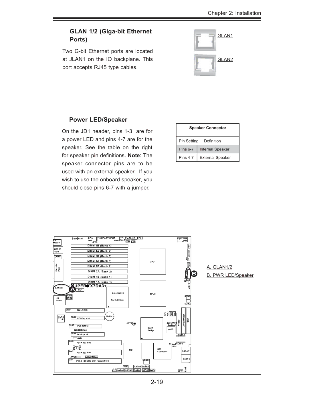
GLAN 1/2 (Giga-bit Ethernet Ports)
Two
Power LED/Speaker
On the JD1 header, pins
apower LED and pins
GLAN1
GLAN2
Speaker Connector
Pin Setting Defi nition
Pins
Pins
KB/
Mouse
USB 0/ 1/2/3
COM1
Parrallel PortJLAN1
LAN1/2
HD
Audio
|
|
| Fan6 | Fan5 |
|
| CPU | Fan7 | J17 | PSF | ||||||
|
|
|
|
|
|
| PWR |
|
| JPW1 | Fan 1 | J3P | JAR | |||
|
|
|
|
|
|
| JPW2 |
|
|
|
| |||||
|
|
|
|
|
|
| DIMM 4B (Bank 4) |
|
|
|
|
|
| |||
|
|
|
|
|
|
|
|
|
|
|
|
|
|
|
|
|
|
|
|
|
|
|
| DIMM 4A (Bank 4) |
|
|
|
|
|
| |||
|
|
|
|
|
|
|
|
|
|
|
|
|
| |||
|
|
|
|
|
|
| DIMM 3B (Bank 3) |
|
|
|
|
|
| |||
|
|
|
|
|
|
|
|
|
|
|
|
|
| |||
|
|
|
|
|
|
| DIMM 3A (Bank 3) |
|
|
|
|
|
| |||
|
|
|
|
|
|
|
|
|
|
|
|
|
| |||
|
|
|
|
|
|
| DIMM 2B (Bank 2) |
|
|
|
|
|
| |||
|
|
|
|
|
|
|
|
|
|
|
|
|
| |||
|
|
|
|
|
|
| DIMM 2A (Bank 2) |
|
|
|
|
|
| |||
|
|
|
|
|
|
| DIMM 1B (Bank 1) |
|
|
|
|
|
| |||
|
|
|
|
|
|
|
|
|
|
|
|
|
| |||
|
|
|
|
|
|
| DIMM 1A (Bank 1) |
|
|
|
|
|
| |||
| SUPER | X7DA3+ |
|
|
|
|
|
|
| |||||||
|
|
|
|
|
|
| ||||||||||
|
|
|
|
|
|
|
| |||||||||
| A | CD1 |
|
|
|
|
|
|
|
|
|
|
| |||
|
|
|
|
|
|
|
|
|
| Greencreek |
|
|
|
|
| |
Audio |
|
|
|
|
|
|
|
|
|
|
|
|
| |||
CTRL |
|
|
|
|
|
| North Bridge |
|
|
|
|
| ||||
|
|
|
|
|
|
|
|
|
|
|
|
|
|
| ||
|
|
|
|
|
|
|
|
|
|
|
|
|
|
|
|
|
CPU1
CPU2
|
| ||
JPW3 |
|
| |
|
|
|
|
|
| Fan1 | |
|
|
|
|
1FJ | FP Control |
| |
|
|
|
|
|
| Fan2 | |
PWLEDSPK |
|
| |
|
| ||
LE1 |
|
| |
|
| ||
|
| JOH1 | |
SGPIO1 | |||
|
|
|
|
|
|
|
|
SGPIO2 | |||
B
A.GLAN1/2
B.PWR LED/Speaker
|
| Slot7 |
| SIMLPIPMI |
|
|
|
|
|
| ||||||||
|
|
|
|
|
|
|
|
|
|
|
|
|
| |||||
|
|
|
|
|
|
|
|
|
|
|
|
|
|
|
|
|
| Battery |
GLAN |
|
|
| Slot6 |
|
|
|
|
| |||||||||
CTLR |
|
|
|
|
|
|
|
|
|
|
|
| ||||||
|
|
|
|
|
|
|
|
|
|
|
|
|
|
|
|
|
| |
|
|
|
|
|
|
|
|
|
|
|
|
|
|
|
|
|
|
|
|
|
|
|
|
|
|
|
|
|
|
|
|
|
|
|
| ||
|
|
| Slot5 |
|
|
|
|
|
|
| ||||||||
|
|
|
|
|
|
|
|
|
|
|
|
|
| |||||
|
|
|
|
|
|
|
|
|
|
|
|
|
|
|
|
|
|
|
|
|
|
|
|
|
|
|
|
|
|
|
|
|
|
|
|
|
|
|
|
|
|
|
|
| 2 | C3 | 2 | C4 |
|
|
|
|
|
|
| |
|
|
|
|
|
| JI | JI |
|
|
|
|
|
|
| ||||
|
|
|
|
|
|
|
|
|
|
|
|
|
|
|
|
|
|
|
|
|
|
| Slot4 |
|
|
|
|
|
|
| |||||||
|
|
|
|
|
|
|
|
|
|
|
|
|
| |||||
|
|
|
|
|
|
|
|
|
|
|
|
|
|
|
|
|
|
|
|
|
|
|
|
|
|
| JWD |
|
|
|
|
|
|
|
|
| |
|
|
|
|
|
|
|
|
|
|
|
|
|
|
|
|
|
|
|
|
|
| Slot3 |
|
|
|
|
| ||||||||||
|
|
|
|
|
|
|
|
|
|
|
| |||||||
|
|
|
|
|
|
|
|
|
|
|
|
|
|
|
|
|
|
|
|
|
|
|
| JPL1 |
| JPL2 |
|
|
|
|
|
|
|
|
| ||
|
|
| Slot2 |
|
|
|
|
| ||||||||||
|
|
|
|
|
|
|
|
|
|
|
| |||||||
|
|
|
|
|
|
|
|
|
|
|
|
|
|
|
|
|
|
|
|
|
|
|
|
|
|
|
|
|
|
|
|
|
|
|
|
|
|
|
|
|
|
|
|
|
|
|
|
| 2 | C1 | 2 | C2 |
|
|
| |
|
|
| JWOR |
|
|
| JI | JI |
|
| ||||||||
|
|
|
|
|
|
|
|
|
|
|
|
|
|
|
|
|
|
|
|
|
| Slot1 | |||||||||||||||
|
|
|
|
|
|
| ||||||||||||
|
|
|
|
|
|
|
|
|
|
|
|
|
|
|
|
|
|
|
|
|
|
|
| CPU Fan2 |
|
|
|
|
|
| |
|
|
|
|
| Fan8 | Fan3 |
| Flash | DE1 | |||
|
|
|
|
|
|
|
|
|
| |||
|
|
|
|
|
|
|
|
| Floppy | Compact | ||
JBT1 |
|
|
|
| JCF1JWF1 | I | ||||||
|
|
|
|
|
| |||||||
|
| South |
|
|
|
|
|
|
|
| ||
|
|
|
|
|
|
|
|
|
| |||
|
|
|
| BIOS |
|
|
|
| ||||
|
| Bridge |
|
|
|
|
|
| ||||
|
|
|
|
|
|
|
|
|
| |||
|
|
|
|
|
|
|
|
|
|
|
|
|
|
|
|
|
|
|
|
|
|
|
|
|
|
|
|
|
|
|
|
|
|
|
|
| ||
|
|
|
|
|
|
|
|
|
|
| ||
|
|
|
|
|
|
|
|
|
|
| ||
PXH |
|
|
| SAS |
| JPS1 |
|
|
|
| ||
|
|
|
|
|
| |||||||
|
|
|
| Controller |
|
|
| |||||
|
|
|
|
|
|
|
|
|
| |||
|
|
|
|
|
|
|
|
|
|
|
| |
|
|
|
|
|
|
|
|
|
| |||
| USB4/5 |
|
|
| ||||||||
|
|
|
|
|
|
| ||||||
|
|
|
|
|
|
|
|
|
|
|
|
|
|
|
|
|
|
|
|
|
|
|
|
|
|
|
|
| SMB |
| SATA4 | SATA5 |
|
|
|
|
|
|
|
|
| |
| JL1 |
|
|
|
|
|
|
|
|
|
| JS10 | Fan4 |
| ||
|
| SATA0 | SATA1 | SATA2 | SATA3 | JWOL |
|
|
|
|
|
|
|
| ||
|
|
|
|
|
|
|
|
|
|
|
|
|
|
|
|
|