Chapter 2: Installation
High Definition Audio (HD Audio)
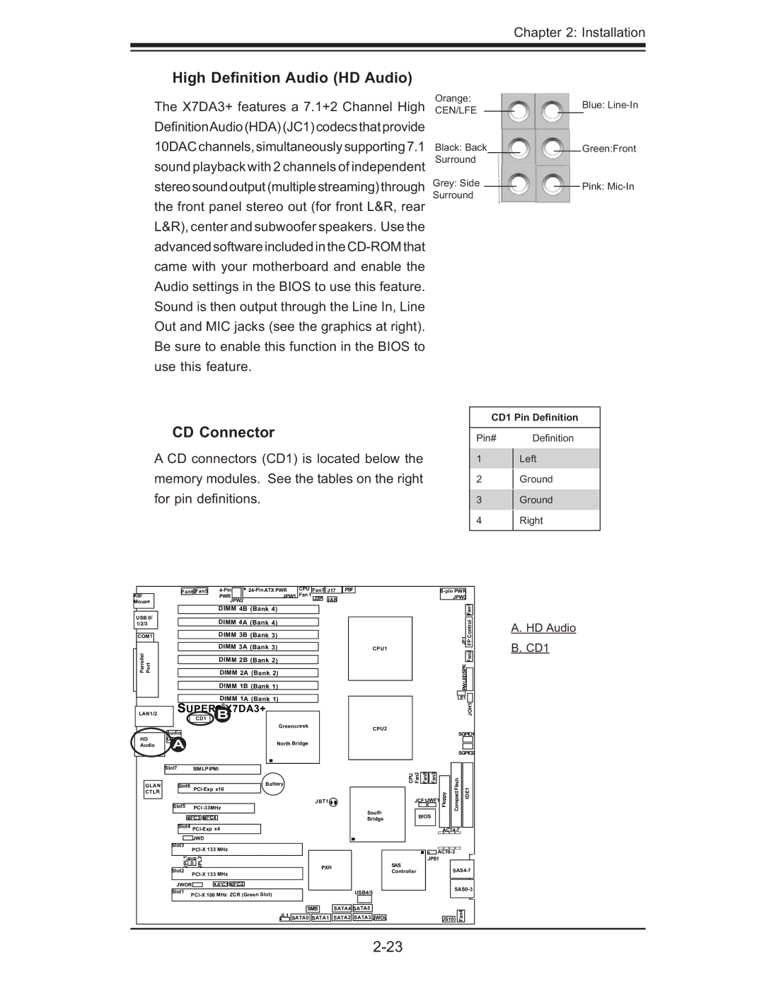
The X7DA3+ features a 7.1+2 Channel High DefinitionAudio(HDA)(JC1)codecsthatprovide 10DACchannels,simultaneouslysupporting7.1 sound playback with 2 channels of independent stereosoundoutput(multiplestreaming)through the front panel stereo out (for front L&R, rear L&R), center and subwoofer speakers. Use the advanced software included in the
Orange:
CEN/LFE
Black: Back
Surround
Grey: Side ![]()
Surround
Blue:
Green:Front
Pink:
CD Connector
A CD connectors (CD1) is located below the memory modules. See the tables on the right for pin defi nitions.
CD1 Pin Definition
Pin# | Defi nition |
1Left
2Ground
3Ground
4 Right
KB/ Mouse
| Fan6 | Fan5 |
|
| CPU | Fan7 |
| J17 | PSF | ||||
|
|
| PWR |
|
| JPW1 | Fan 1 |
|
|
|
|
|
|
|
|
|
| JPW2 |
|
|
| J3P |
| JAR |
|
| |
|
|
|
|
|
|
|
|
| |||||
|
|
|
|
|
|
|
|
|
|
|
|
|
|
|
|
| DIMM 4B (Bank 4) |
|
|
|
|
|
|
| |||
JPW3 |
Fan1 |
USB 0/ 1/2/3
COM1
Parrallel PortJLAN1
LAN1/2
SUPER
CD1
DIMM 4A (Bank 4)
DIMM 3B (Bank 3)
DIMM 3A (Bank 3)
DIMM 2B (Bank 2)
DIMM 2A (Bank 2)
DIMM 1B (Bank 1)
DIMM 1A (Bank 1)
X7DA3+ B
CPU1
| 1JF |
| FP Control |
|
|
|
|
|
|
| Fan2 |
| PWLEDSPK |
|
|
|
|
| |
LE1 |
| ||
|
|
| JOH1 |
A. HD Audio
B. CD1
HD Audio
|
| Greencreek |
Audio |
|
|
CTRL |
|
|
A | North Bridge | |
|
| |
CPU2
SGPIO1 |
SGPIO2 |
|
| Slot7 |
| SIMLPIPMI |
|
|
|
|
|
| ||||||||
|
|
|
|
|
|
|
|
|
|
|
|
|
| |||||
|
|
|
|
|
|
|
|
|
|
|
|
|
|
|
|
|
| Battery |
GLAN |
|
|
| Slot6 |
|
|
|
|
| |||||||||
CTLR |
|
|
|
|
|
|
|
|
|
|
|
| ||||||
|
|
|
|
|
|
|
|
|
|
|
|
|
|
|
|
|
| |
|
|
|
|
|
|
|
|
|
|
|
|
|
|
|
|
|
|
|
|
|
|
|
|
|
|
|
|
|
|
|
|
|
|
|
| ||
|
|
| Slot5 |
|
|
|
|
|
|
| ||||||||
|
|
|
|
|
|
|
|
|
|
|
|
|
| |||||
|
|
|
|
|
|
|
|
|
|
|
|
|
|
|
|
|
|
|
|
|
|
|
|
|
|
|
|
|
|
|
|
|
|
|
|
|
|
|
|
|
|
|
|
| 2 | C3 | 2 | C4 |
|
|
|
|
|
|
| |
|
|
|
|
|
| JI | JI |
|
|
|
|
|
|
| ||||
|
|
|
|
|
|
|
|
|
|
|
|
|
|
|
|
|
|
|
|
|
|
| Slot4 |
|
|
|
|
|
|
| |||||||
|
|
|
|
|
|
|
|
|
|
|
|
|
| |||||
|
|
|
|
|
|
|
|
|
|
|
|
|
|
|
|
|
|
|
|
|
|
|
|
|
|
| JWD |
|
|
|
|
|
|
|
|
| |
|
|
|
|
|
|
|
|
|
|
|
|
|
|
|
|
|
|
|
|
|
| Slot3 |
|
|
|
|
| ||||||||||
|
|
|
|
|
|
|
|
|
|
|
| |||||||
|
|
|
|
|
|
|
|
|
|
|
|
|
|
|
|
|
|
|
|
|
|
|
| JPL1 |
| JPL2 |
|
|
|
|
|
|
|
|
| ||
|
|
| Slot2 |
|
|
|
|
| ||||||||||
|
|
|
|
|
|
|
|
|
|
|
| |||||||
|
|
|
|
|
|
|
|
|
|
|
|
|
|
|
|
|
|
|
|
|
|
|
|
|
|
|
|
|
|
|
|
|
|
|
|
|
|
|
|
|
|
|
|
|
|
|
|
| 2 | C1 | 2 | C2 |
|
|
| |
|
|
| JWOR |
|
|
| JI | JI |
|
| ||||||||
|
|
|
|
|
|
|
|
|
|
|
|
|
|
|
|
|
|
|
|
|
| Slot1 | |||||||||||||||
|
|
|
|
|
|
| ||||||||||||
|
|
|
|
|
|
|
|
|
|
|
|
|
|
|
|
|
|
|
|
|
|
|
| CPU Fan2 |
|
|
|
|
|
| |
|
|
|
|
| Fan8 | Fan3 |
| Flash | DE1 | |||
|
|
|
|
|
|
|
|
|
| |||
|
|
|
|
|
|
|
|
| Floppy | Compact | ||
JBT1 |
|
|
|
| JCF1JWF1 | I | ||||||
|
|
|
|
|
| |||||||
|
| South |
|
|
|
|
|
|
|
| ||
|
|
|
|
|
|
|
|
|
| |||
|
|
|
| BIOS |
|
|
|
| ||||
|
| Bridge |
|
|
|
|
|
| ||||
|
|
|
|
|
|
|
|
|
| |||
|
|
|
|
|
|
|
|
|
|
|
|
|
|
|
|
|
|
|
|
|
|
|
|
|
|
|
|
|
|
|
|
|
|
|
|
| ||
|
|
|
|
|
|
|
|
|
|
| ||
|
|
|
|
|
|
|
|
|
|
| ||
PXH |
|
|
| SAS |
| JPS1 |
|
|
|
| ||
|
|
|
|
|
| |||||||
|
|
|
| Controller |
|
|
| |||||
|
|
|
|
|
|
|
|
|
| |||
|
|
|
|
|
|
|
|
|
|
|
| |
|
|
|
|
|
|
|
|
|
| |||
| USB4/5 |
|
|
| ||||||||
|
|
|
|
|
|
| ||||||
|
|
|
|
|
|
|
|
|
|
|
|
|
|
|
|
|
|
|
|
|
|
|
|
|
|
|
|
| SMB |
| SATA4 | SATA5 |
|
|
|
|
|
|
|
|
| |
| JL1 |
|
|
|
|
|
|
|
|
|
| JS10 | Fan4 |
| ||
|
| SATA0 | SATA1 | SATA2 | SATA3 | JWOL |
|
|
|
|
|
|
|
| ||
|
|
|
|
|
|
|
|
|
|
|
|
|
|
|
|
|