iDP3221 User’s Manual
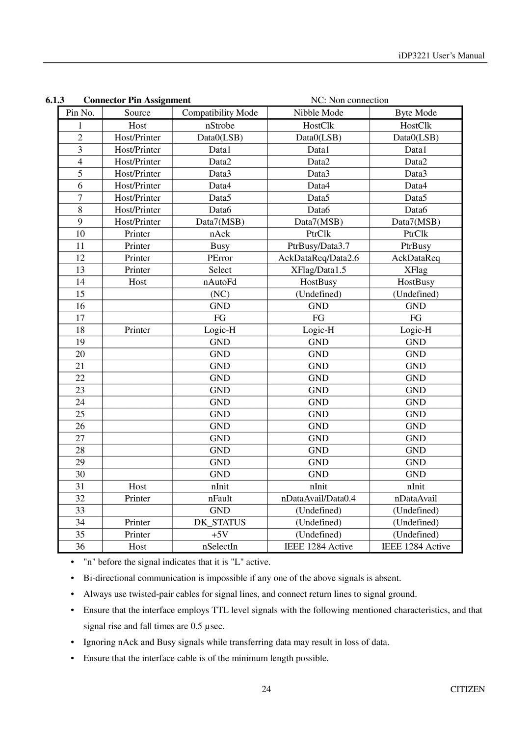
6.1.3 Connector Pin Assignment | NC: Non connection | ||||
| Pin No. | Source | Compatibility Mode | Nibble Mode | Byte Mode |
| 1 | Host | nStrobe | HostClk | HostClk |
| 2 | Host/Printer | Data0(LSB) | Data0(LSB) | Data0(LSB) |
| 3 | Host/Printer | Data1 | Data1 | Data1 |
| 4 | Host/Printer | Data2 | Data2 | Data2 |
| 5 | Host/Printer | Data3 | Data3 | Data3 |
| 6 | Host/Printer | Data4 | Data4 | Data4 |
| 7 | Host/Printer | Data5 | Data5 | Data5 |
| 8 | Host/Printer | Data6 | Data6 | Data6 |
| 9 | Host/Printer | Data7(MSB) | Data7(MSB) | Data7(MSB) |
| 10 | Printer | nAck | PtrClk | PtrClk |
| 11 | Printer | Busy | PtrBusy/Data3.7 | PtrBusy |
| 12 | Printer | PError | AckDataReq/Data2.6 | AckDataReq |
| 13 | Printer | Select | XFlag/Data1.5 | XFlag |
| 14 | Host | nAutoFd | HostBusy | HostBusy |
| 15 |
| (NC) | (Undefined) | (Undefined) |
| 16 |
| GND | GND | GND |
| 17 |
| FG | FG | FG |
| 18 | Printer | |||
| 19 |
| GND | GND | GND |
| 20 |
| GND | GND | GND |
| 21 |
| GND | GND | GND |
| 22 |
| GND | GND | GND |
| 23 |
| GND | GND | GND |
| 24 |
| GND | GND | GND |
| 25 |
| GND | GND | GND |
| 26 |
| GND | GND | GND |
| 27 |
| GND | GND | GND |
| 28 |
| GND | GND | GND |
| 29 |
| GND | GND | GND |
| 30 |
| GND | GND | GND |
| 31 | Host | nInit | nInit | nInit |
| 32 | Printer | nFault | nDataAvail/Data0.4 | nDataAvail |
| 33 |
| GND | (Undefined) | (Undefined) |
| 34 | Printer | DK_STATUS | (Undefined) | (Undefined) |
| 35 | Printer | +5V | (Undefined) | (Undefined) |
| 36 | Host | nSelectIn | IEEE 1284 Active | IEEE 1284 Active |
•"n" before the signal indicates that it is "L" active.
•
•Always use
•Ensure that the interface employs TTL level signals with the following mentioned characteristics, and that signal rise and fall times are 0.5 µ sec.
•Ignoring nAck and Busy signals while transferring data may result in loss of data.
•Ensure that the interface cable is of the minimum length possible.
24 | CITIZEN |