iDP3221 User’s Manual
7.3.2Data Configuration
t
Mark
b0, b1, b2, • • • •
Space | (1) | (2) | (3) |
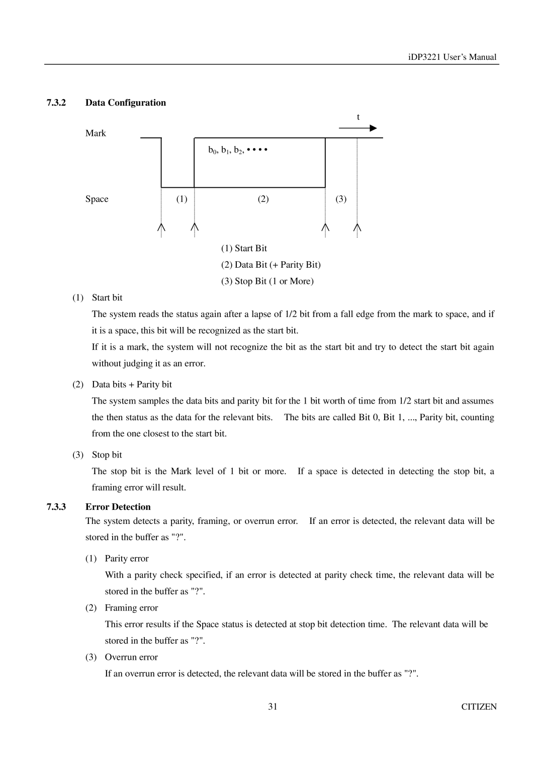
(1)Start Bit
(2)Data Bit (+ Parity Bit)
(3)Stop Bit (1 or More)
(1)Start bit
The system reads the status again after a lapse of 1/2 bit from a fall edge from the mark to space, and if it is a space, this bit will be recognized as the start bit.
If it is a mark, the system will not recognize the bit as the start bit and try to detect the start bit again without judging it as an error.
(2)Data bits + Parity bit
The system samples the data bits and parity bit for the 1 bit worth of time from 1/2 start bit and assumes the then status as the data for the relevant bits. The bits are called Bit 0, Bit 1, ..., Parity bit, counting from the one closest to the start bit.
(3)Stop bit
The stop bit is the Mark level of 1 bit or more. If a space is detected in detecting the stop bit, a framing error will result.
7.3.3Error Detection
The system detects a parity, framing, or overrun error. If an error is detected, the relevant data will be stored in the buffer as "?".
(1)Parity error
With a parity check specified, if an error is detected at parity check time, the relevant data will be stored in the buffer as "?".
(2)Framing error
This error results if the Space status is detected at stop bit detection time. The relevant data will be stored in the buffer as "?".
(3)Overrun error
If an overrun error is detected, the relevant data will be stored in the buffer as "?".
31 | CITIZEN |
