iDP3221 User’s Manual
8.DRAWER KICK-OUT CONNECTOR, POWER CONNECTOR
8.1Drawer Kick-Out Connector
8.1.1Specifications of Drawer Kick-Out Connector
(1)Drawer
Outputs a pulse specified with ESC p. The status of SW (+) can be checked with pin 34 on the parallel interface connector, or with the DLE EOT, GS a, and GS r commands through the serial/parallel interface.
(2)Electrical characteristics
1)Drive voltage: 24 V DC
2)Drive current: 0.8 A at maximum (Within 510 ms)
3) Switch signal level: "L" = 0 to 0.5 V, "H" = 3 to 5 V
8.1.2Connector's Pin Configuration
No. | Signal |
| Function |
|
1 | FG | Frame Ground |
| |
2 | DRAWER 1 | Drawer 1 drive signal |
| |
3 | DRSW | Drawer switch input |
| |
4 | VDR | Drawer drive power |
| |
5 | DRAWER 2 | Drawer 2 drive signal |
| |
6 | GND | Common ground on the circuit |
| |
|
|
|
|
|
| Connector used | : | ||
| Applicable connector | : | ||
CAUTION : • No output is made while printing.
•The drawers 1 and 2 cannot be driven simultaneously.
•A solenoid used for the drawer should be of 36Ω or more. An output current should be kept below 0.8 A. Use beyond this limit cannot be assured.
•This connector cannot be connected to a telephone line. Do not connect other than the solenoid.
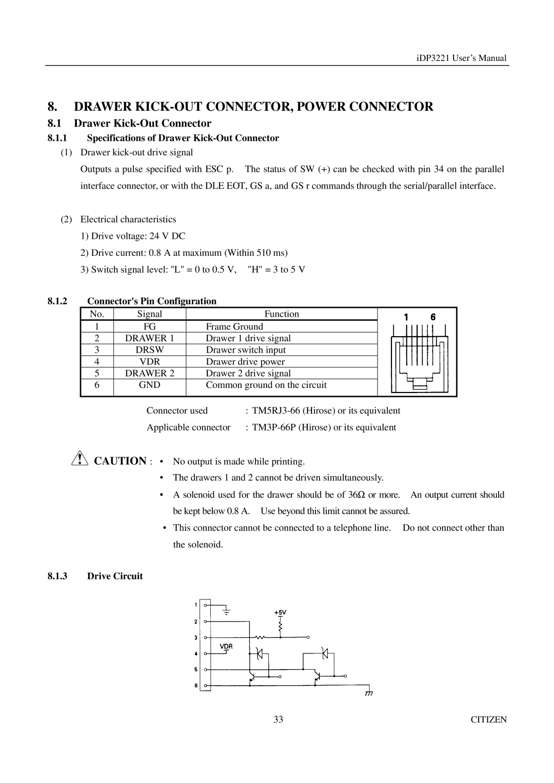
8.1.3Drive Circuit
33 | CITIZEN |