2101 Field Wizard
Section 2 Preparation and Installation
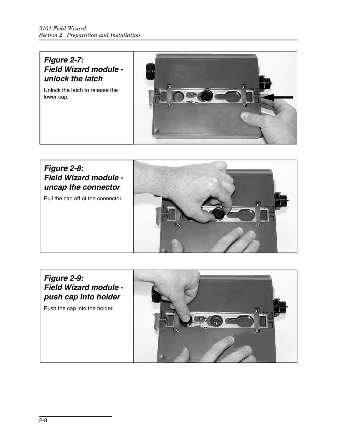
Figure
Field Wizard module - unlock the latch
Unlock the latch to release the lower cap.
Figure
Field Wizard module - uncap the connector
Pull the cap off of the connector.
Figure
Field Wizard module - push cap into holder
Push the cap into the holder.