2101 Field Wizard
Section 3 Operation
Sensor Diagnostics – When you press F5 DIAG from the Site Setup display, the diagnostic screen shown in Figure
Figure 3-15 Sensor Diagnostics Display
| After a momentary delay, during which the Field Wizard |
| requests the report from the 2100 Series module, a screen con- |
| taining diagnostic results for the selected module’s sensors will |
| appear. Use the four directional arrow keys to scroll through the |
| information. |
| Once you have viewed the information, press F6 EXIT to exit to |
| the Site Setup display. |
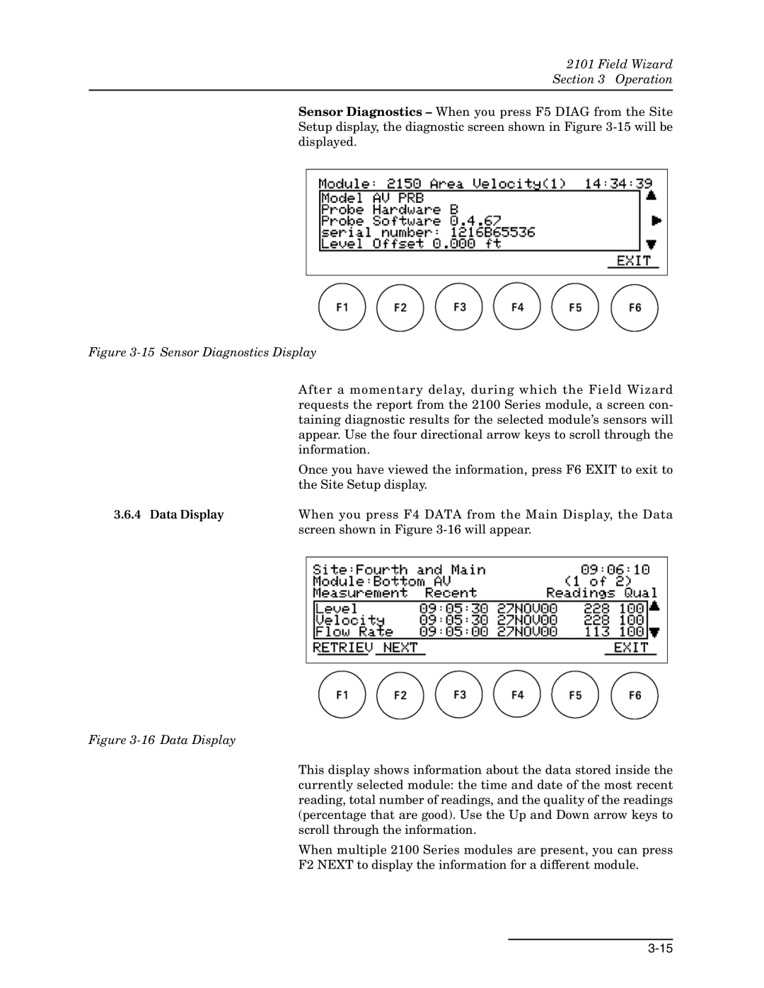
3.6.4 Data Display | When you press F4 DATA from the Main Display, the Data |
| screen shown in Figure |
Figure 3-16 Data Display
This display shows information about the data stored inside the currently selected module: the time and date of the most recent reading, total number of readings, and the quality of the readings (percentage that are good). Use the Up and Down arrow keys to scroll through the information.
When multiple 2100 Series modules are present, you can press
F2 NEXT to display the information for a different module.