| 2101 Field Wizard |
| Section 3 Operation |
|
|
| To view the data retrieval log, press F2 LOG. The display will be |
| similar to that shown in Figure |
| 3.5.2. |
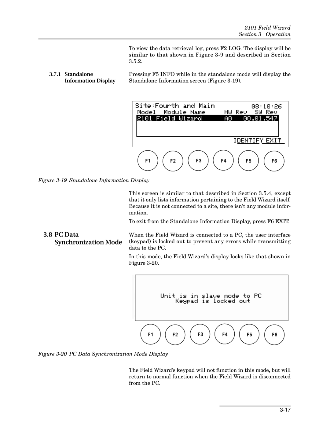
3.7.1 Standalone | Pressing F5 INFO while in the standalone mode will display the |
Information Display | Standalone Information screen (Figure |
Figure 3-19 Standalone Information Display
3.8PC Data Synchronization Mode
This screen is similar to that described in Section 3.5.4, except that it only lists information pertaining to the Field Wizard itself. Because it is not connected to a site, there isn’t any module infor- mation.
To exit from the Standalone Information Display, press F6 EXIT.
When the Field Wizard is connected to a PC, the user interface (keypad) is locked out to prevent any errors while transmitting data to the PC.
In this mode, the Field Wizard’s display looks like that shown in Figure
Figure 3-20 PC Data Synchronization Mode Display
The Field Wizard’s keypad will not function in this mode, but will return to normal function when the Field Wizard is disconnected from the PC.