2101 Field Wizard
Section 3 Operation
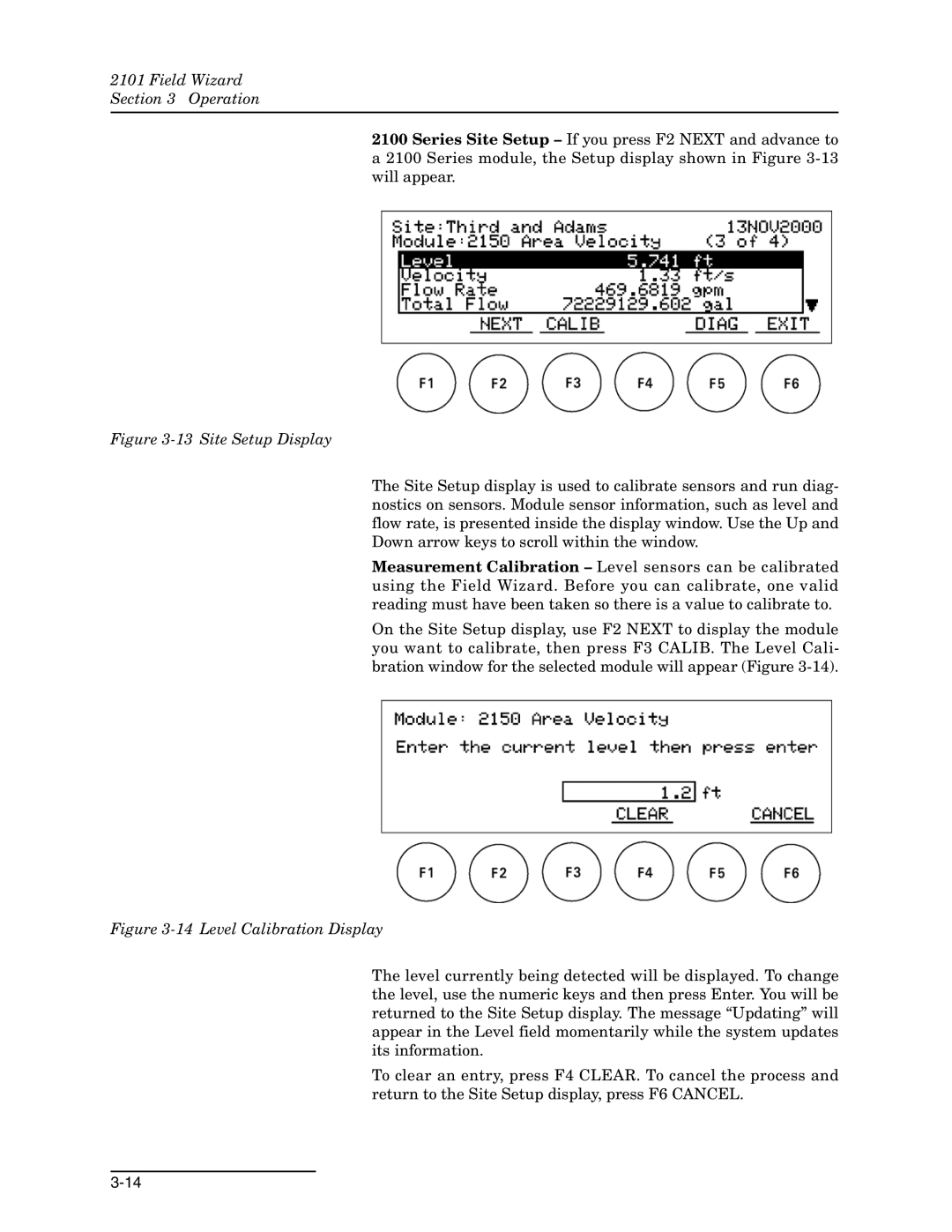
2100 Series Site Setup – If you press F2 NEXT and advance to a 2100 Series module, the Setup display shown in Figure
Figure 3-13 Site Setup Display
The Site Setup display is used to calibrate sensors and run diag- nostics on sensors. Module sensor information, such as level and flow rate, is presented inside the display window. Use the Up and Down arrow keys to scroll within the window.
Measurement Calibration – Level sensors can be calibrated using the Field Wizard. Before you can calibrate, one valid reading must have been taken so there is a value to calibrate to.
On the Site Setup display, use F2 NEXT to display the module you want to calibrate, then press F3 CALIB. The Level Cali- bration window for the selected module will appear (Figure
Figure 3-14 Level Calibration Display
The level currently being detected will be displayed. To change the level, use the numeric keys and then press Enter. You will be returned to the Site Setup display. The message “Updating” will appear in the Level field momentarily while the system updates its information.
To clear an entry, press F4 CLEAR. To cancel the process and return to the Site Setup display, press F6 CANCEL.