2101 Field Wizard |
| |
Section 3 | Operation |
|
|
|
|
|
| Press F1 RETRIEV to retrieve the data for the displayed module. |
|
| You will be advanced to the Retrieve Data Display, described in |
|
| Section 3.6.1. |
|
| Press F6 EXIT to return to the Main Display. |
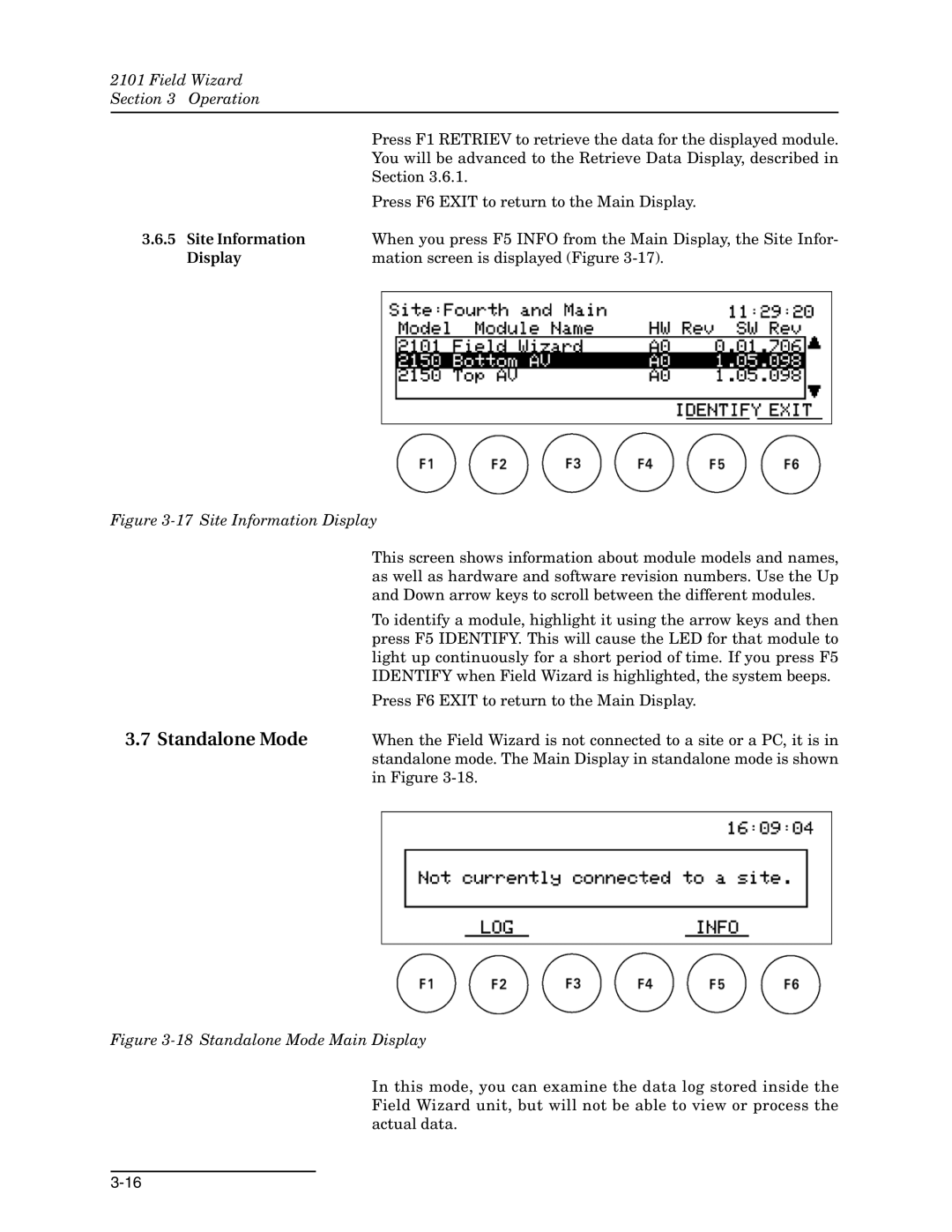
3.6.5 | Site Information | When you press F5 INFO from the Main Display, the Site Infor- |
| Display | mation screen is displayed (Figure |
Figure 3-17 Site Information Display
3.7 Standalone Mode
This screen shows information about module models and names, as well as hardware and software revision numbers. Use the Up and Down arrow keys to scroll between the different modules.
To identify a module, highlight it using the arrow keys and then press F5 IDENTIFY. This will cause the LED for that module to light up continuously for a short period of time. If you press F5 IDENTIFY when Field Wizard is highlighted, the system beeps.
Press F6 EXIT to return to the Main Display.
When the Field Wizard is not connected to a site or a PC, it is in standalone mode. The Main Display in standalone mode is shown in Figure
Figure 3-18 Standalone Mode Main Display
In this mode, you can examine the data log stored inside the Field Wizard unit, but will not be able to view or process the actual data.